• Welcome to the new NAXJA Forum! If your password does not work, please use "Forgot your password?" link on the log-in page. Please feel free to reach out to [email protected] if we can provide any assistance.

My 89 comanche project

Frank Z said:
Disconnect the trackbar on the axle and leave the drag link connected. Have an assistant turn the steering wheel and the body will move over the axle. Much easier than trying to push the body by hand.

yes, BUT it doesn't turn far enough. (I already tried that)

for some reason it isn't matching up correctly...
 
hmm those uppers won't last long if you wheel it.

000128n.jpg
 
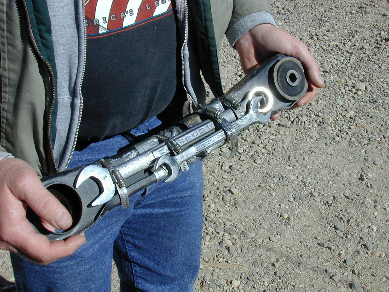
first, that's a lower control arm.

second, these uppers are HEAVILY reinforced. I do believe that they will last quite a long time.
 
OH REALLY? Forgot chrysler made the uppers beefier I thought they were made with the same sheet metal?


:D
 
RyanM said:
OH REALLY? Forgot chrysler made the uppers beefier I thought they were made with the same sheet metal?
:D

uh...idk if you even LOOKED at how I did them, but these are based off of stocks, but extended, and reinforced by angle iron and plating on the outside of the weld point. the angle iron extends from about 1" behind the axle-side bushing to the same on the upper side bushing.

measurement on these is 15.75" and they should have been 16" IMO.

they'll last, I don't rock climb, go 90mph through mud, or ham on my rigs. slow and steady is more fun and less expensive.
 
jeepcomj said:
uh...idk if you even LOOKED at how I did them, but these are based off of stocks, but extended, and reinforced by angle iron and plating on the outside of the weld point. the angle iron extends from about 1" behind the axle-side bushing to the same on the upper side bushing.

The problem is the stock arms are actually designed to twist a little if they are beyond the range of the rubber bushings (not under normal/on-road use!). You can actually twist them by hand.

By reinforcing the center, you are putting all the stress on the non-reinforced sheet metal ends. They will eventually tear. IIRC Someone did something similar to yours on here a couple years ago with destructive results.

Now if you NEVER wheel it and flex it out, it may hold up just fine.
 
Last edited:
TRAILREADYXJ said:
The problem is the stock arms are actually designed to twist a little if they are beyond the range of the rubber bushings (not under normal/on-road use!). You can actually twist them by hand.

By reinforcing the center, you are putting all the stress on the non-reinforced sheet metal ends. They will eventually tear. IIRC Someone did something similar to yours on here a couple years ago with destructive results.

Now if you NEVER wheel it and flex it out, it may hold up just fine.

*shrug* it's not like I designed them to be permanent additions to the jeep. the goal WAS to make my uppers out of tubing, I just didn't have the time to do so.
 
TRAILREADYXJ said:
The problem is the stock arms are actually designed to twist a little if they are beyond the range of the rubber bushings (not under normal/on-road use!). You can actually twist them by hand.

By reinforcing the center, you are putting all the stress on the non-reinforced sheet metal ends. They will eventually tear. IIRC Someone did something similar to yours on here a couple years ago with destructive results.

Now if you NEVER wheel it and flex it out, it may hold up just fine.

something like this? :D :D :D


IMG_0001.jpg
 
Last edited:
alright, so I got the front axle back in, and all the associated stuff. now I just need the shocks, and to stretche the brake line farther.
also I will need to do a tierod flip on this thing. it is do-able. the tires are toed in a bit, so that will be adjusted as well.
I think I may need to extend the upper control arms a bit more too.
n69205416_32154045_7815.jpg

n69205416_32154047_8355.jpg

n69205416_32154048_8612.jpg

here it is just set down
n69205416_32154049_8873.jpg

n69205416_32154050_9136.jpg

n69205416_32154051_9394.jpg

hooking up steering etc.
n69205416_32154052_9658.jpg

n69205416_32154053_9926.jpg

cleaned the CAD and got it working too
n69205416_32154055_439.jpg

made the swaybar links, solid ones for now
n69205416_32154056_697.jpg

and the calipers are on, but there's not enough room in the brake line for 6.5" of lift
n69205416_32154057_977.jpg

the brake line bent back really easy, but I can't pull any more through
n69205416_32154058_1245.jpg
 
just takin it up a rock. that's as far as I could go...the brake line was too far stretched
n69205416_32154059_1511.jpg

n69205416_32154060_1777.jpg

n69205416_32154061_2041.jpg

n69205416_32154062_2315.jpg

n69205416_32154063_2582.jpg

this is the amount of clearance at full turn that I have between the control arm and the tire
n69205416_32154064_2848.jpg

and between the tire and the fender flare
n69205416_32154065_3110.jpg


so the front sits at 39" of height from the ground to the fender flare
that's 23.5" from the center of the hub to the bottom of the fender flare, compared to the stock being 17" or something like that. so true lift was 5.5 inches roughly. I'm OK with that.

the rear will be lifted SO in the rear this week, and will sit about 2" higher than the front when done. then all I have to do is front shocks, all brake lines need extended or replaced, and do something about the steering arms...
 
Burlington WI
Posted: Mon Jul 30, 2007 10:08 pm Post subject: more pics today...
n69205416_32167046_9311.jpg

drove it over what's left of our conveyor belts...
n69205416_32167047_9718.jpg

n69205416_32167048_52.jpg

kinda a pose pic
n69205416_32167049_395.jpg

I climbed my rock pile
n69205416_32167050_735.jpg

n69205416_32167051_1081.jpg

me happy
n69205416_32167052_1411.jpg

now the rear needs a lift
n69205416_32167053_1741.jpg
 
sprung it over

n69205416_32182565_3099.jpg

n69205416_32182566_3317.jpg
everything disconnected
n69205416_32182567_3538.jpg

handy heavy duty frame stands
n69205416_32182568_3755.jpg

new u-bolts
n69205416_32182570_4201.jpg

axle out
n69205416_32182571_4431.jpg

wet spots are wd40 from me squirting the brake line ends to remove the brake line...it was a halfassed line so...
n69205416_32182572_4653.jpg

removed axle truck view
n69205416_32182573_4876.jpg

axle set to figure out stance, centering, and pinion angles
n69205416_32182574_5098.jpg

let me say that metric tonne rear springs offer ALOT more lift than normal ones
n69205416_32182575_5321.jpg

using the jack to set pinion angle...decided to put it on jackstands as this method wouldn't offer me turning ability on the driveshaft to find binding.
n69205416_32182577_5771.jpg

new ubolts and perches, this is how it will be set up and I'll be welding in the shock mounts/perches seperately.
n69205416_32182579_6234.jpg

it's NOT welded yet
n69205416_32182580_6458.jpg
 
thats how far the yoke is out...less than an inch is in
n69205416_32182581_6690.jpg

I think this is where it needs to be located, but the tranny has to drop or driveshaft lengthened or both.
n69205416_32182583_7142.jpg


so I had some tranny drop spacers made from 1"OD, 1/4" wall, 1/2" OD tube...1.25" ones.
only broke 2 bolts off, the other one is removed thanks to my dad's welding skills (built it up and removed with vice grips) and the other one will be done next.

here's pics...it had studs on the driver's side frame for the crossmember, they had to go for the drop kit to work...so they did but the nut for one broke off.
fixed it this way.
n69205416_32233488_7072.jpg

n69205416_32233489_7311.jpg

n69205416_32233490_7545.jpg

then just welded that stud down...

spacers 1" OD, 1/4" walls, 1/2" ID
n69205416_32233492_8014.jpg

n69205416_32233493_8249.jpg

completely installed crossmember
n69205416_32233494_8481.jpg

n69205416_32233495_8714.jpg

n69205416_32233497_9196.jpg

d-shaft will gained 1.25" or more of input on the slip-yoke from the drop
n69205416_32233496_8951.jpg

n69205416_32233498_9432.jpg


so it's dropped.

in the morning I will re-center the axle, then use the pinion angle gauge to set the rear axle to match the output shaft, pull axle after tac-welding it in, then have dad full weld it paint it and reinstall it.

will be doing rear brakes tomorrow too and also dropping the e-brake assembly.

whatcha think?
 
got angle gauge, set pinion angle.

removed axle after tac-welding perches on

n69205416_32239815_7693.jpg

n69205416_32239816_8050.jpg

n69205416_32239817_8362.jpg


welder is not up to snuff anymore, so it will have to be welded @ my grandpa's shop on saturday morning. then I can weld my shock mounts on it and get everything permanently mounted


and that's where it's at. it needs to be welded up (tomorrow morning I hope) and then I can put it all back together and all that will be left is rear brake line extension/plumbing, front brake line extension, and cab corners. it will run and drive with the driveshaft that's in it, but I'd like to get a longer one made sooner than later.
 
Back
Top