Talyn
NAXJA Forum User
- Location
- Radford, Communistwealth of Virginia
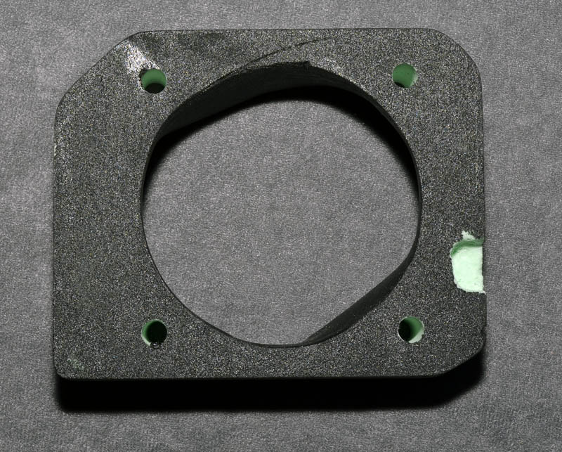
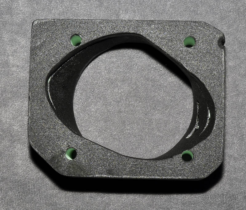
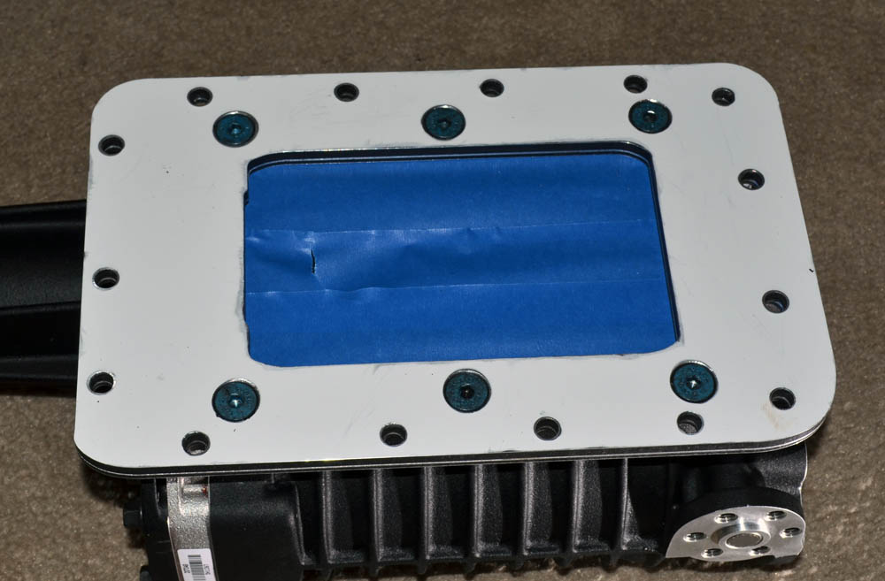
Its called Dibond, which is a trade name. Aluminum faces, polyethylene core. The pieces I cut are from 1 piece of 1/4" bonded to a piece of 1/8" to give me approximately 3/8". It cuts easily and is great for stuff like this.
Using emachineshop.com I can get a standard 1" 70mm throttle body spacer for $74 shipped, which actulaly isn't too bad. Adding a tap on each side just about doubles the price. I can tap it myself for that much.. and anodizing adds about $300.. LOL.
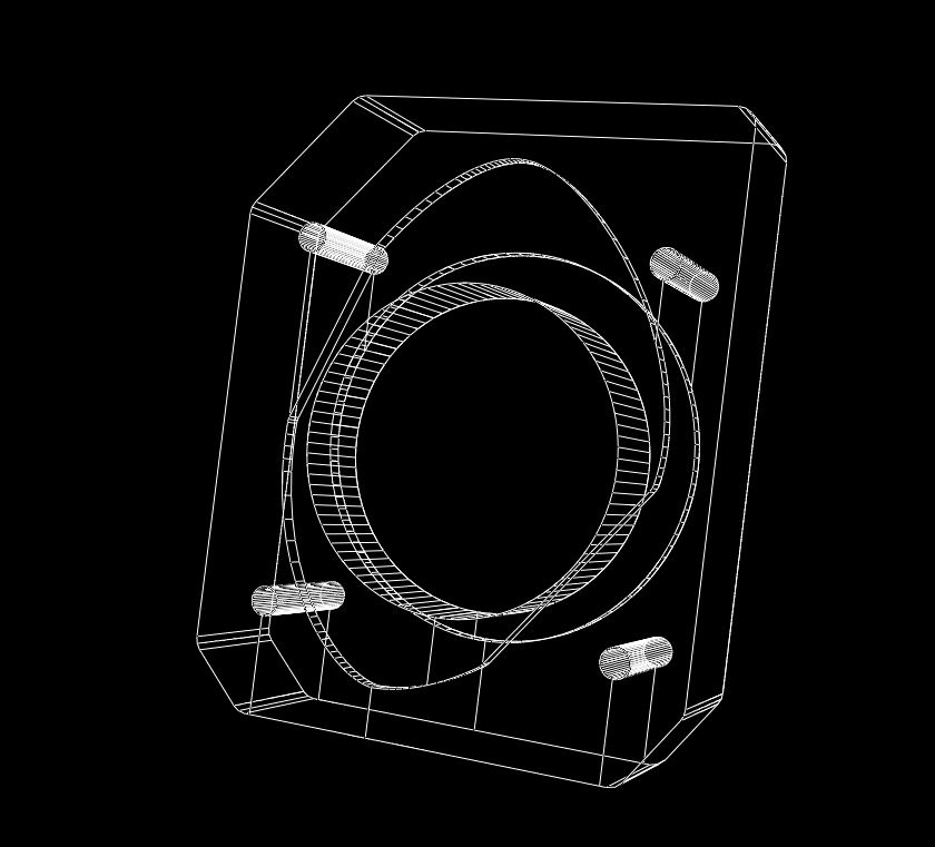
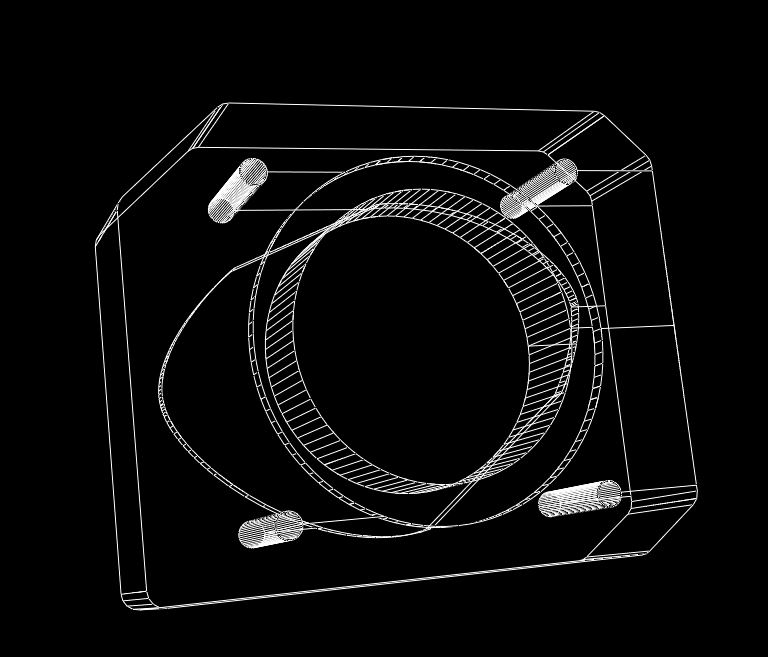
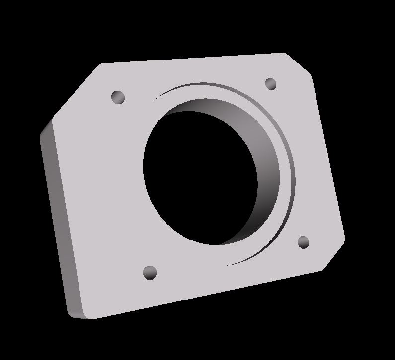
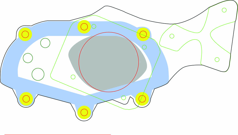
Now, for a 1" spacer with an oval on the front to avoid the inlet edges and a 70mm circle on the back is $80 shipped, then I would have to hand blend it myself... that may be the way to go..
Something a little more intricate and larger, where the front side would blend with the MP90 inlet and then a circle on the backside that would match the TB is around $160, but I would have to hand blend the interior.
Using emachineshop.com I can get a standard 1" 70mm throttle body spacer for $74 shipped, which actulaly isn't too bad. Adding a tap on each side just about doubles the price. I can tap it myself for that much.. and anodizing adds about $300.. LOL.
Now, for a 1" spacer with an oval on the front to avoid the inlet edges and a 70mm circle on the back is $80 shipped, then I would have to hand blend it myself... that may be the way to go..
Something a little more intricate and larger, where the front side would blend with the MP90 inlet and then a circle on the backside that would match the TB is around $160, but I would have to hand blend the interior.
Last edited: