• Welcome to the new NAXJA Forum! If your password does not work, please use "Forgot your password?" link on the log-in page. Please feel free to reach out to [email protected] if we can provide any assistance.

How to Wire Off Road Lights?

That would be freaking awesome!!!

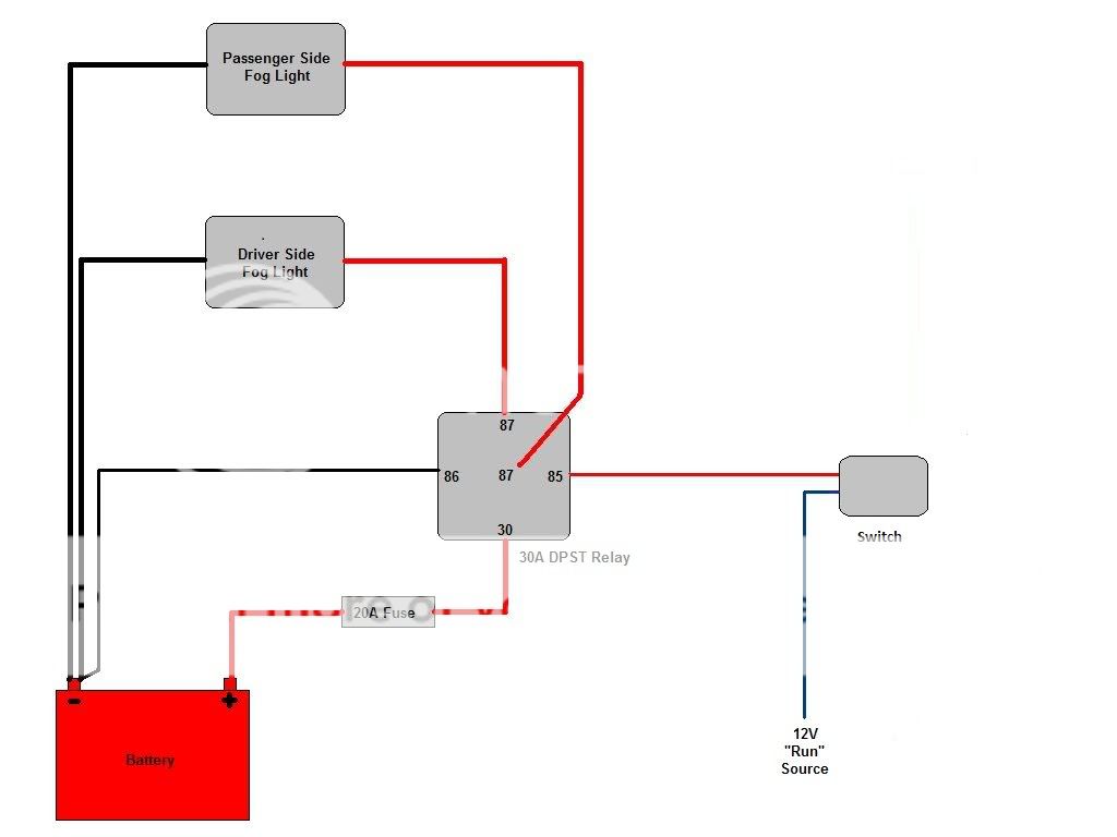
Alright, well here's what I got. I'm running 4 lights off of 2 relays and one switch, so your configuration may vary.

100 feet of White, 14 gauge primary wire (Item 1114102)
http://www.delcity.net/store/14-gauge/p_181400.h_181789.a_1.t_1

Vinyl Insulated Step-Down Butt Connectors (Item 422115)
http://www.delcity.net/cartviewitem?item=422115&search=422115
(because not every wire, as you'll see, will be 14 gauge)

Ring Terminals, 1/4" Stud (Item 452145)
http://www.delcity.net/cartviewitem?item=452145&search=452145

Female Push-On Terminals, 1/4" (Item 492005)
http://www.delcity.net/cartviewitem?item=492005&search=492005

Dual 87 Pin, Normally Open Relays (Item 73996)
http://www.delcity.net/cartviewitem?item=73996&search=73996

DPST (Double pole, Single Throw) Rocker Switch (Item 73392)
http://www.delcity.net/cartviewitem?item=73392&search=73392
(Double pole, meaning two input poles, single throw, meaning it's either on or it's off)

Mini Fuse Holders (2 for me), 12 gauge, 30 Amp max (Item 78385)
http://www.delcity.net/cartviewitem?item=78385&search=78385

Mini Fuses (Item 77205)
http://www.delcity.net/cartviewitem?item=77205&search=77205
(I got 20 amp)

Quick Connect Female Terminals (Item 925735)
http://www.delcity.net/cartviewitem?item=925735&search=925735

Quick Connect Male Terminals (Item 929875)
http://www.delcity.net/cartviewitem?item=929875&search=929875

Body for Female Terminals, 4 contact (Item 970485)
http://www.delcity.net/cartviewitem?item=970485&search=970485

Body for Male Terminals, 4 contact (Item 970495)
http://www.delcity.net/cartviewitem?item=970495&search=970495

Like I said, it's different for everyone, but that's what I bought! As well as some loom for wire management.
 
Sounds intense! I'll definitely take something like that into consideration. I just received my order, and the relays have an 87 contact, and an 87a contact. I ordered this one because the site lists it as having dual 87 contacts. Will the 87 and 87a function as a normal 87? I just want to be able to have all 4 lights going into the 2 relays without having to combine wires.
Like was mentioned the 87A is the normally closed side of a relay. If it says 87A it is a normal relay. Double check your order to make sure you ordered the dual 87 relays. If they messed up call them, and they will make it right. I got a bad prewired relay harness (somthing I could fix myself) that I had ordered months ago, but just noticed the other day. They where going to send a replacement right away, but I was ordering some additional items, and asked if I could just have the shipping waved instead of the replacement. It was no problem.
 
Like was mentioned the 87A is the normally closed side of a relay. If it says 87A it is a normal relay. Double check your order to make sure you ordered the dual 87 relays. If they messed up call them, and they will make it right. I got a bad prewired relay harness (somthing I could fix myself) that I had ordered months ago, but just noticed the other day. They where going to send a replacement right away, but I was ordering some additional items, and asked if I could just have the shipping waved instead of the replacement. It was no problem.

The serial numbers listed online for the ones I bought are the same serial numbers that are on the relays, so I'm pretty confident they will work. On XCM's diagram (I've PM'd him this same question), he has a small wire going from pin 30 to pin 85 (he made a mistake in the drawing I think). What does that wire do? Am I supposed to have two wires connected to pin 85 then? How does the relay itself get grounded?
 
There are two ways to run your switch side you can set it up like normal where the switch switches 12v on/off to control the relay.

WiringDiagram.jpg


Or you can switch the ground side. The 12v will always be going through the coil, but nothing will happen untill you complete the circuit with the ground.

WiringDiagramSwitchingGround.jpg


This is the way he was showing how to do it. If you have a lighted switch it will not work when wired this way.
 
Ok, thanks a lot, that explains it I believe. I'm going to set it up so:

87 pin - 1 light each
86 pin - grounded near the relay
85 pin - switch (I'm not doing the 12V run source thing)
30 pin - coming from the battery, with the fuse in between

That makes the most sense to me, and eliminates splitting wires.

That'll work right?
 
I've hit a snag with the wiring though...got no light. Here's how I have everything laid out:

I have two dual 87 pin, normally open relays.

4 lights, with one power wire each. Lights are grounded on the rack.
2 lights for each relay, one wire going into each 87 pin.
Pin 86 of the relay goes to ground.
Pin 85 of the relay goes to the switch.
Pin 30 of the relay comes from the + terminal of the battery.

The wires off of the 85 pins are the only wires I have going into the switch. Is that what my problem is? Do I need a "run source" wire going into the switch from somewhere in the ACC system or something?
Yes the switches you bought should have four connections on them wired on pairs. You will have one side to the relay, and the other side needs to be to a 12v source. Whether or not you choose a constant hot, hot only when the parking lights are on, or hot only when the key is on is up to you, but you need 12v to drive the relay.
 
Yes the switches you bought should have four connections on them wired on pairs. You will have one side to the relay, and the other side needs to be to a 12v source. Whether or not you choose a constant hot, hot only when the parking lights are on, or hot only when the key is on is up to you, but you need 12v to drive the relay.

Where do I get this 12v run source? My switch is DPST, it has 4 studs. Two running from the relays, so right now I have two open. Is there a way to split the wire coming from the battery, put one end in 30 and one in what is currently grounded, then ground at the switch instead?

^ I guess kinda like the illustration above. That will work? With the split wire and switch grounded instead of the relays?
 
Last edited:
On your switch you will have four blades, 2,3,5,6.


2 -> 12v source of your choice (Toggles Relay #1)
3 -> post 85 on Relay #1
5 -> 12v source of your choice (Toggles Relay #2)
6 -> post 85 on Relay #2

You can splice both 2 and 5 together, then into your 12v source (ACC or Constant). This will toggle both relays, and turn on all four lights, with the flip of the switch.

ACC = On with key, when you turn your key off, your lights will not work.

Constant = On at all times. This will allow you to run the lights without the key turned on.

Electricity needs to flow in a circle. Think of this circle starting and ending in your battery, and the wiring you are doing has basically two circles (pretending only one light is hooked up for simplicity).

Circle 1
Battery (+) -> ACC/Constant 12v -> switch 2/5 -> switch 3/6 -> relay 85 -> relay 86 -> chassis -> battery (-)

The toggle switch between 2/5 and 3/6 opens (off position) the circle preventing the flow of electricity, when closed (on position) the circle is completed and the flow of energy continues.

Circle 2
battery (+) -> fuse -> relay 30 -> relay 87 -> light -> chassis -> battery (-)

The gap between Relay 30 and Relay 87 is a switch. This switch completes Circle 2, but uses the electromagnet between relay 85 and 86 rather than your finger to toggle on/off.

By completing Circle 1 (switch ON) you energize the electromagnet that closes Circle 2, and turns the lights on. When you open Circle 1 (switch OFF), the electromagnet opens Circle 2, and the lights turn off.

If you wanted to get fancy, picture if you will your four lights across the front of your rack.

1 - 2 - 3 - 4

Relay #1 = outboard lights 1/4
30 -> 30amp fuse to battery
85 -> Pin 3 on switch
86 -> Chassis
87 -> Light 1 -> chassis
87 -> Light 4 -> chassis

Relay #2 = inboard lights 2/3
30 -> 30amp fuse to battery
85 -> Pin 6 on switch
86 -> Chassis
87 -> Light 2 -> chassis
87 -> Light 3 -> chassis

Switch
Pin 2 -> 12v Constant (Cig Lighter)
Pin 3 -> Relay #1 85
Pin 5 -> 12v ACC (on with ignition switch)
Pin 6 -> Relay #2 85

Wiring this way gives you a choice to run either 2 or 4 lights with the single switch. With the key off/out the light switch would turn on/off the two outboard lights (1/4). Key on/run the switch would turn on/off all four lights. This would lessen the drain on your battery by using only two lights with the key off/out. When the key is on/run, you will run all four lights (1/2/3/4) at the same time.

Edit...
You can play around with the 12v sources for pins 2/5 on the switch. ANY 12v source will provide the "trigger" circuit with the power needed to toggle the relay on/off. As mentioned above, you could wire it to a 12v trigger source off the parking lamps, only allowing the auxiliary lights to work when the parking lamps are on. Really, you can trigger the relays with anything... dome light on/off, right turn signal flashing, rear windshield washer... ANYTHING with a 12v source to complete Circle 1 will do!
 
Last edited:
Dude, that's a ton of info! Right now I'm sitting in the Jeep with the center console piece off, looking aty cigarette lighters. The PO had two Hellas installed on the front bumper with the factory fog light switch. It looks like he used one of the cigarette lighter wires as his run source. Can I do the same with my other cigarette lighter on the other side of the console? Just combine the two 12v run source pins right off the switch, then run that wire and splice it into the cigarette lighter wire?
 
Yes?

If you want all four lights to work without the key being on/run, you can take pins 2/5 from your switch and splice them together, this splice can be as close as you want to the switch. Then take that spliced line and splice it into the 12v source.

There are other ways of wiring the relays to clean things up a bit, but the info listed above is going to be the easiest to wrap your head around.

If I were you, and wanting to toggle all four lights with key off/out I would do the following

Relay #1 = outboard lights 1/4
30 -> 30amp fuse to battery
85 -> Pin 3 on switch
86 -> Chassis
87 -> Light 1 -> chassis
87 -> Light 4 -> chassis

Relay #2 = inboard lights 2/3
30 -> 30amp fuse to battery
85 -> Pin 6 on switch
86 -> Chassis
87 -> Light 2 -> chassis
87 -> Light 3 -> chassis

Switch
Pin 2 -> Spliced to Pin 5 -> 12v Constant (Cig Lighter)
Pin 3 -> Relay #1 85
Pin 5 -> Spliced to Pin 2 -> 12v Constant (Cig Lighter)
Pin 6 -> Relay #2 85

This way if one fuse or relay fails, you will be running either 1/4 or 2/3. You can also switch around the use of your 87's and run 1/3 and 2/4 or 1/2 and 3/4.
 
Last edited:
Well, the lights are on and working just fine! I took a few pictures of the wiring, but nothing really exciting. Hopefully in the next few days I'll be able to take some good pictures of the whole Jeep with the new lights and refurb'd rack. Now that I'm back at school, I probably won't be updating as often since I don't have any money and I don't have much time to work on it
sad.gif


If anyone wants pictures/descriptions of the wiring process, post up or PM me, I'll do my best to explain!
 
Back
Top