bzauche
NAXJA Forum User
- Location
- Dahlonega, GA
You don't always NEED a relay like I don't have one for my rear lights on my rack. Some switches can handle the load for the lights but some cannot and some power needs are beyond the limits of a switch and a relay is needed.
So if I were to run two switches, I'd be more likely to be able to not use a relay?
Solid state wiring (without relays) doesnt make you stupid. If you take everything into consideration, use the right switch and wire thickness, it'll work and be safe. Many trophy trucks dont use relays due to them failing under extensive constant vibration.
You can also run smaller load stuff (like say, an engine mounted small LED light) without relays.... LED stuff doesnt draw a big load.
Electrical... its complicated.
I'm realizing more and more that electrical is probably the most complicated thing I've had to work with...If I were to split up the lights into two sections, running two switches, and some big fat wire, would that work without relays? I think not using a relay would be best for my limited electrical knowledge...
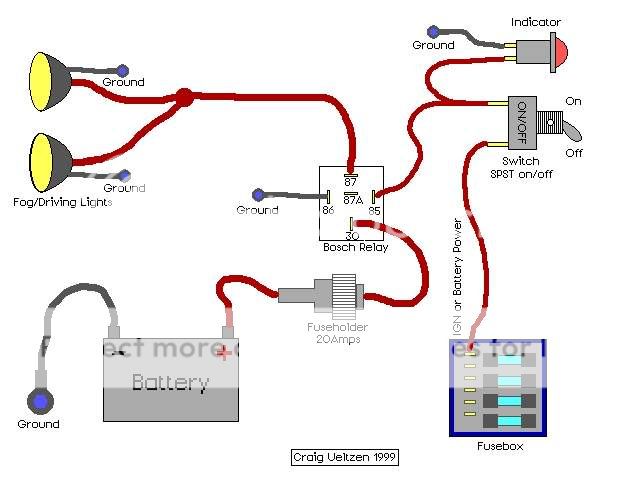


 If I were to run 4 lights (2 sets of what ZJ's illustration is basically), I'll need 2 relays, 2 fuseholders, 2 switches (can I use just 1?), and a bunch of wire. Correct?
