• Welcome to the new NAXJA Forum! If your password does not work, please use "Forgot your password?" link on the log-in page. Please feel free to reach out to [email protected] if we can provide any assistance.

Introducing Little Orphan Annie and Myself

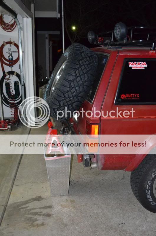
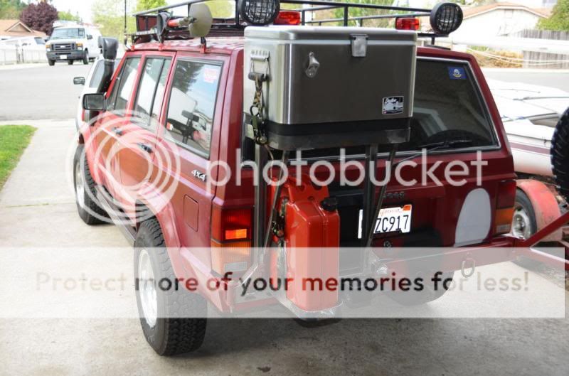
man you did an awesome job in the back!! i love it. wish i had the tools and time to make something like that. looks killer. and i like the air defector too, very neat idea

Thanks cencal. I appreciated the compliments.
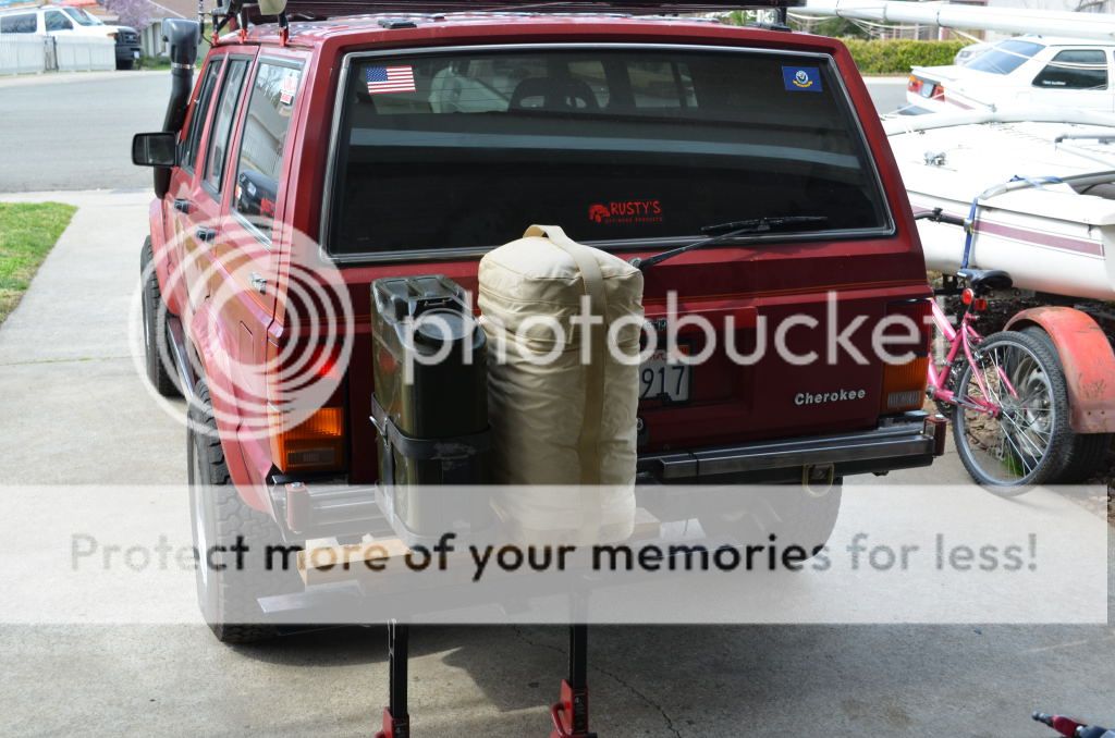
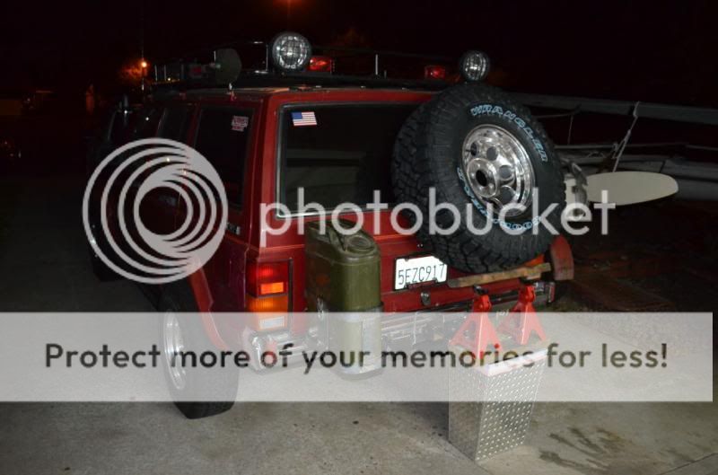
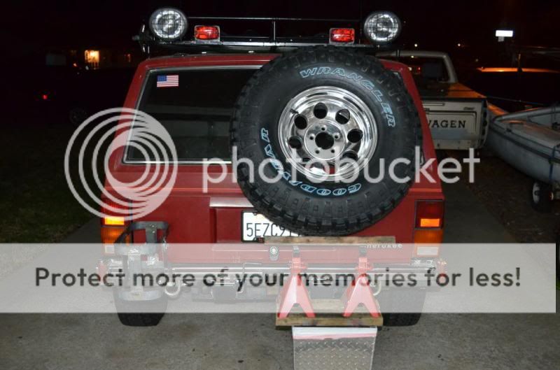
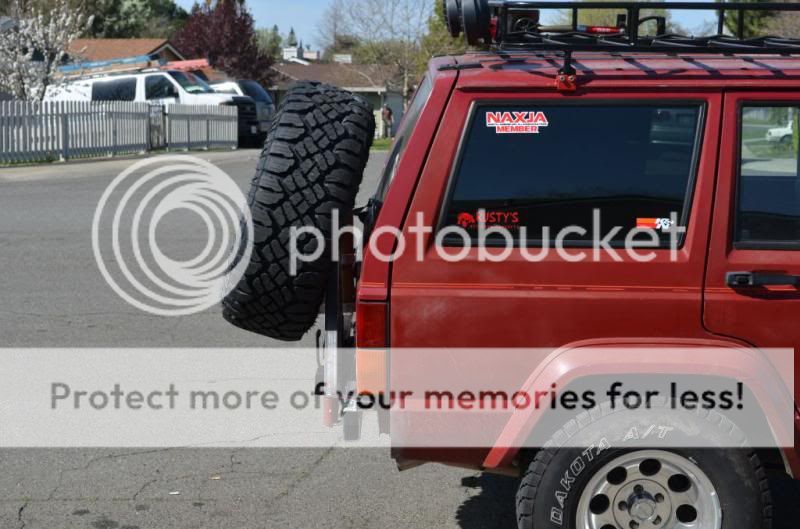
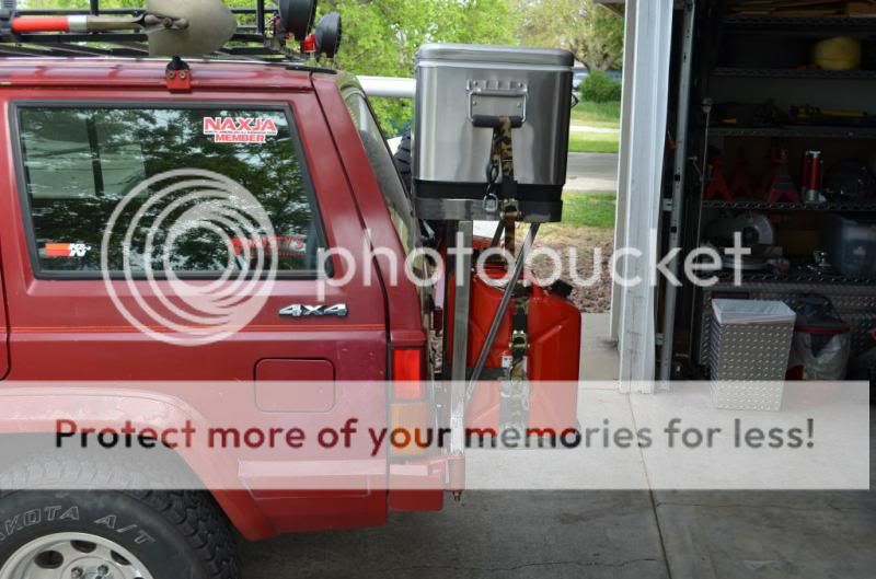
And I did a considerable amount of work on the rear bumper this past week and managed to get most of it burnt in on the weekend.

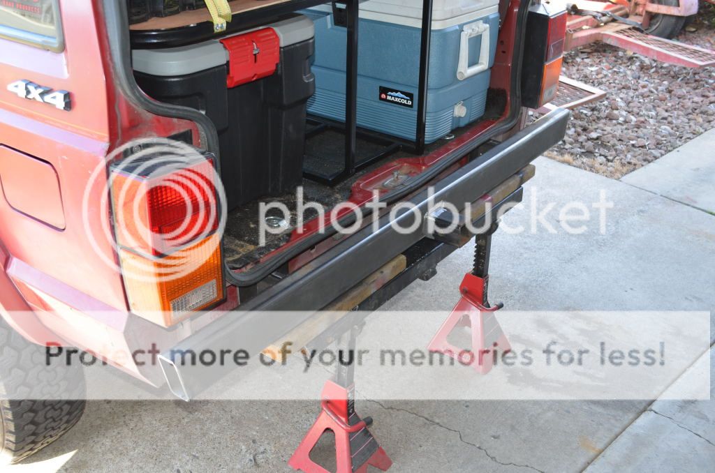
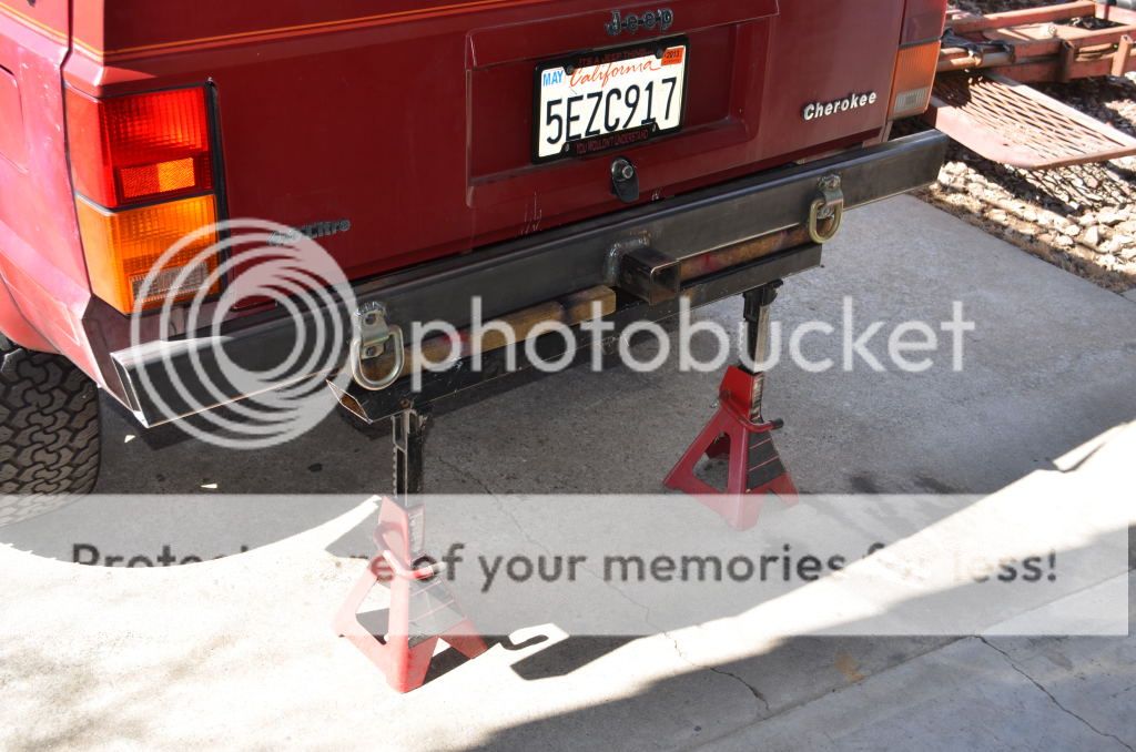
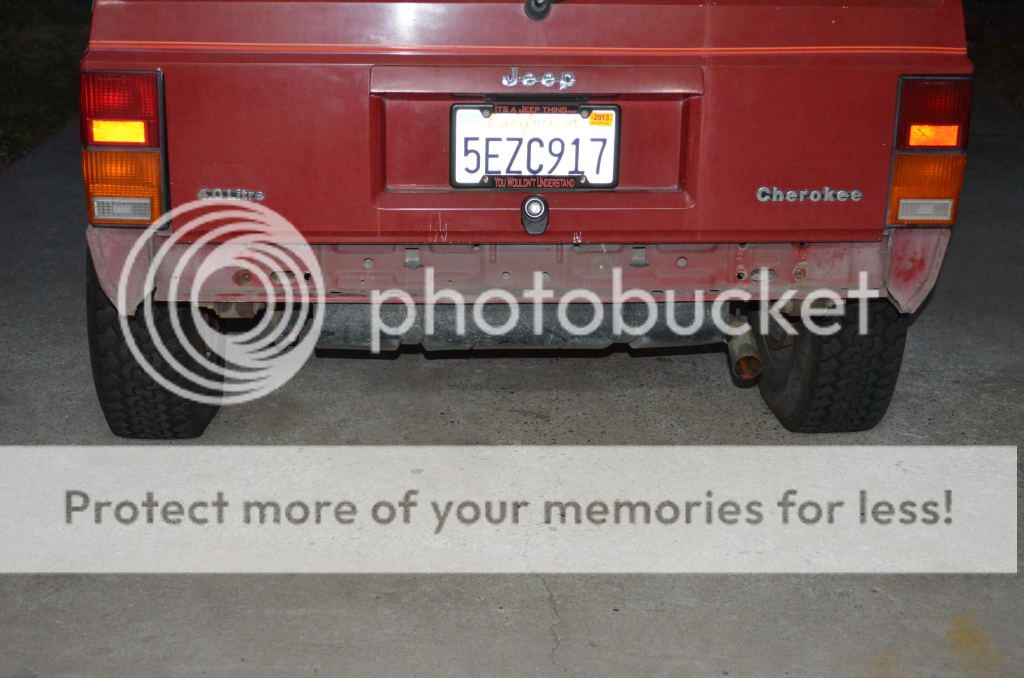
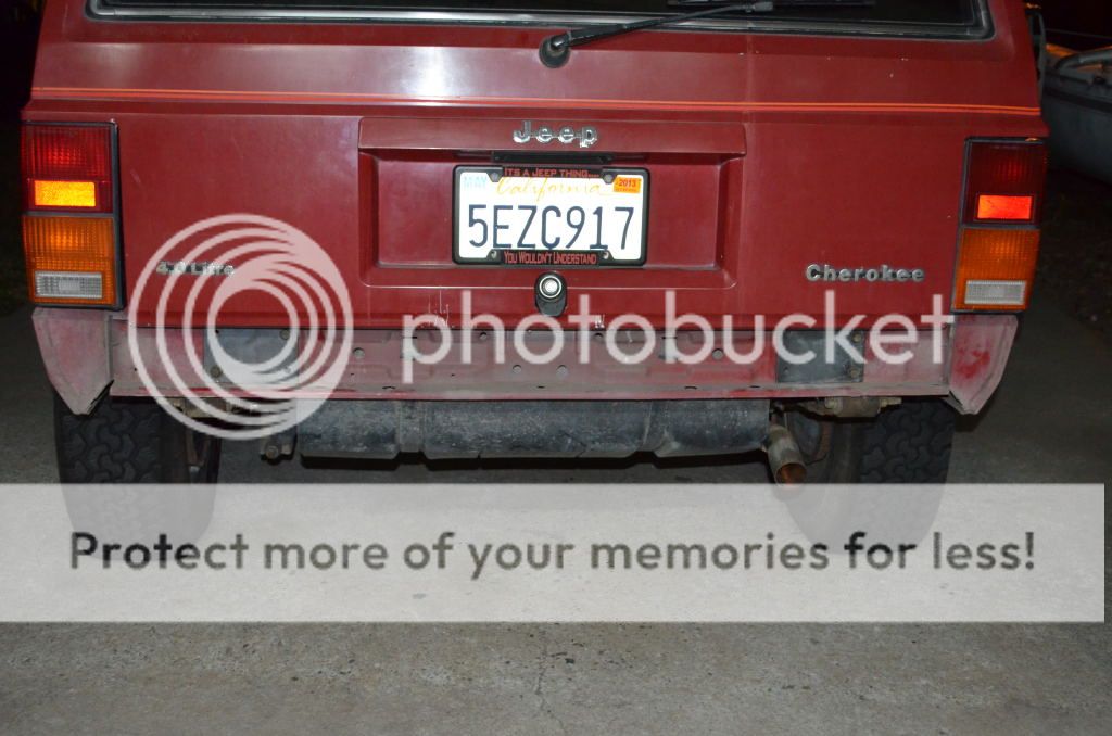
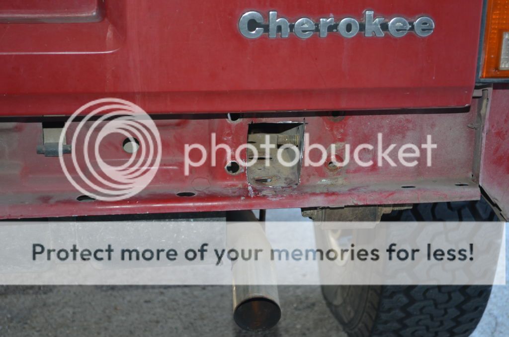
As per usual, first thing to do is get the old bumper off:

RearBumper01.jpg


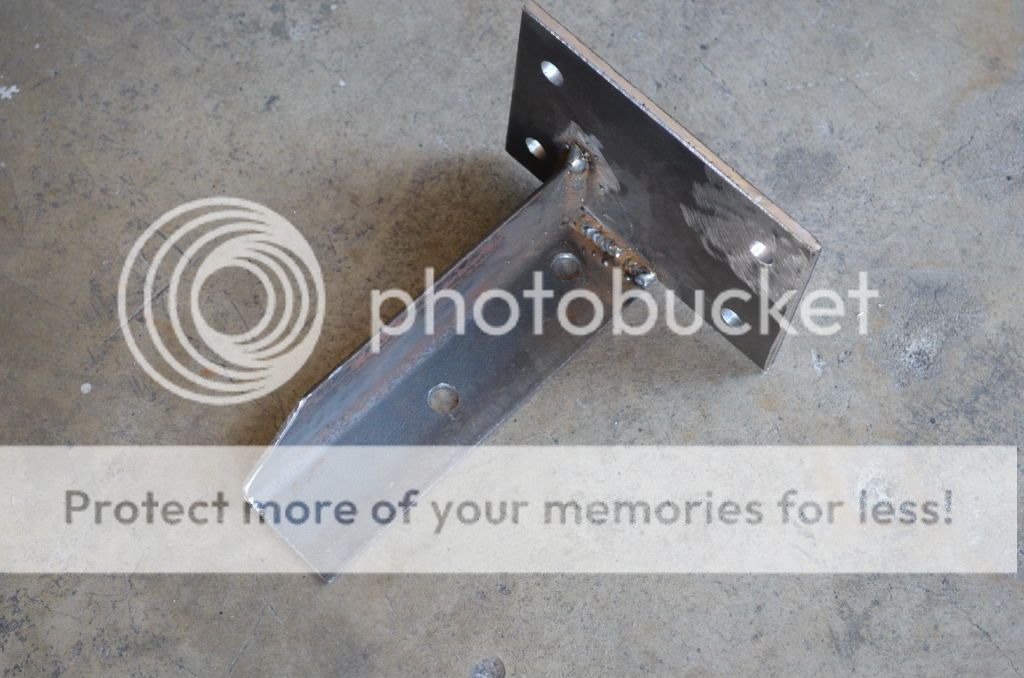
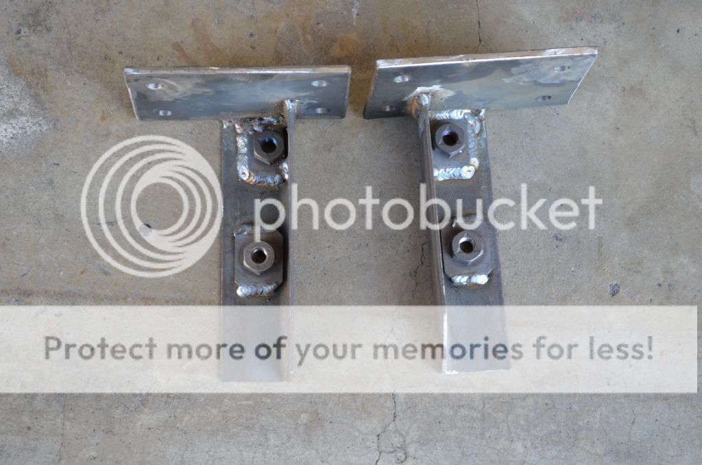
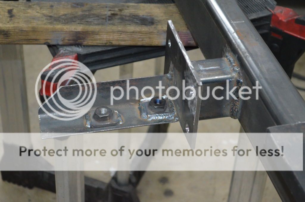
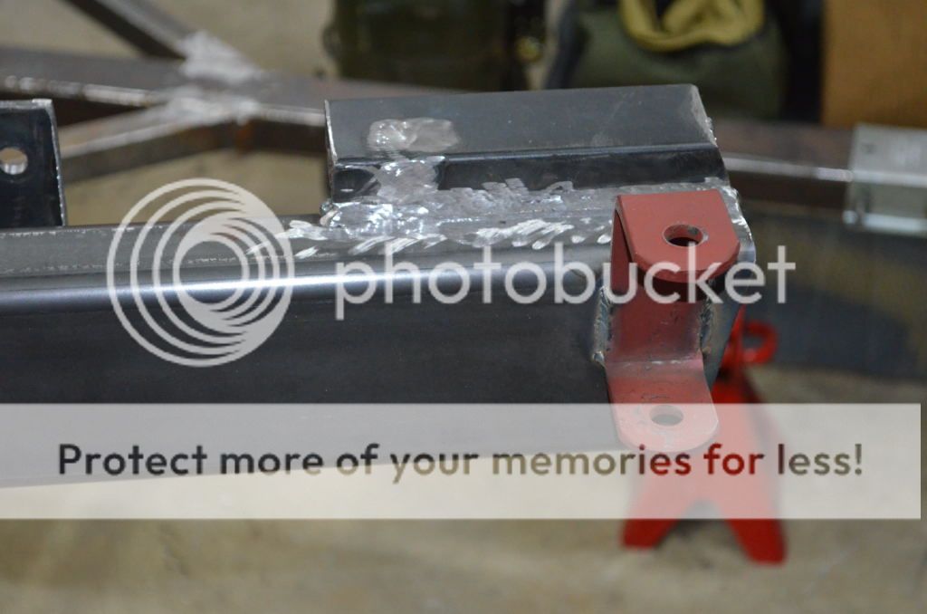
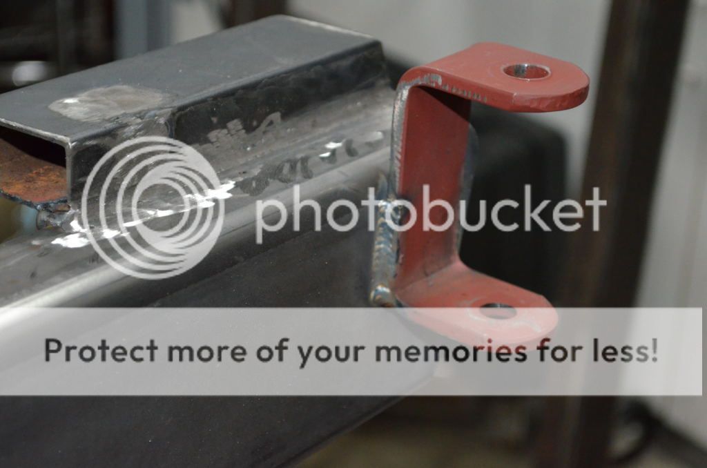
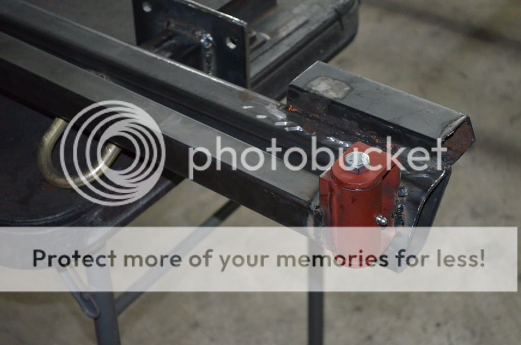
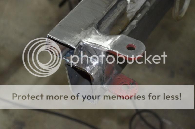
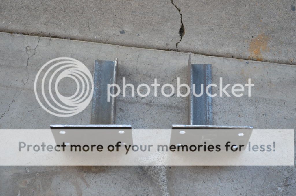
Make some mounting plates out of 1/4" plate:

RearBumper02.jpg


RearBumper03.jpg


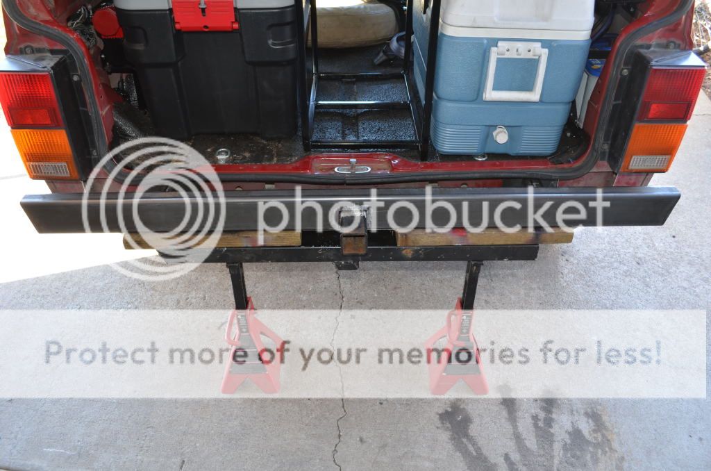
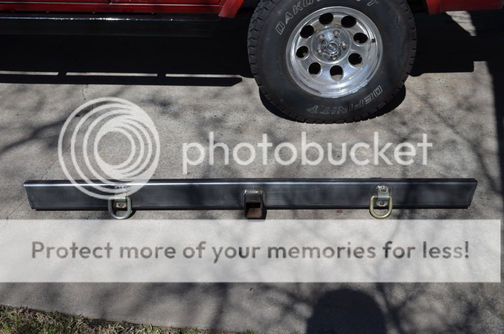
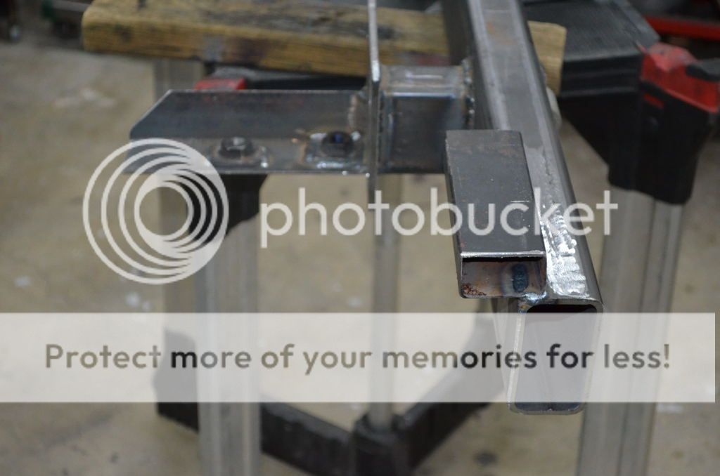
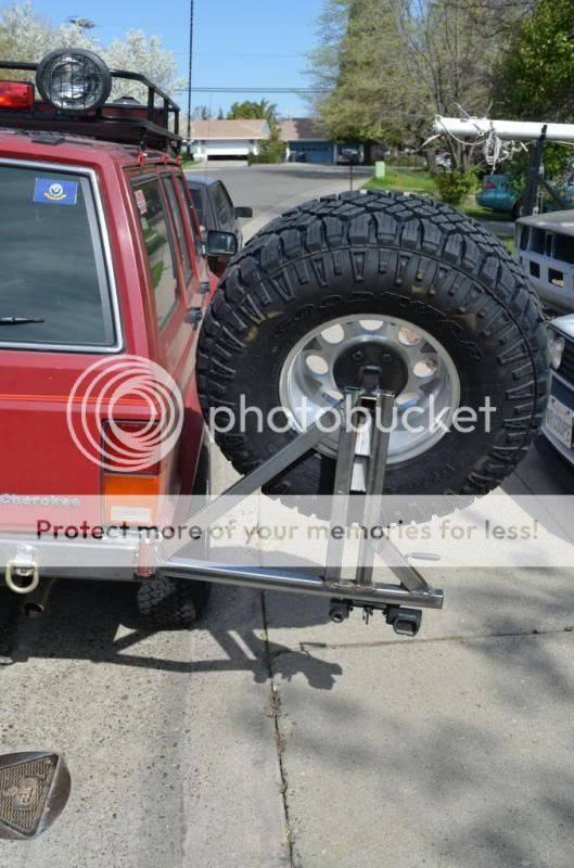
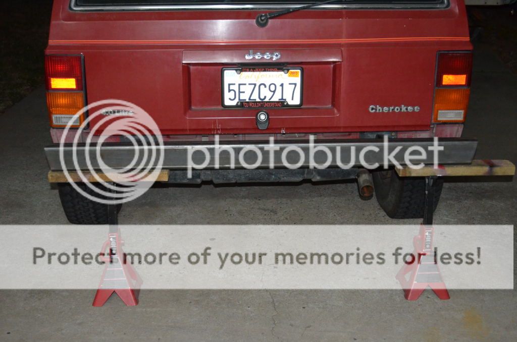
And mock the bumper bar into location for measurements:
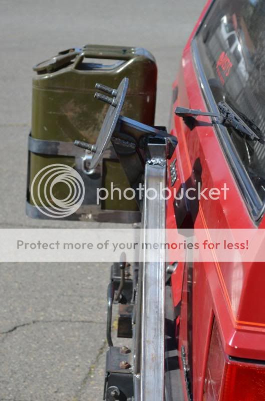
The bar is 2x4x.25" rec tubing, cut 65" long and with a slight angle cut at each end to match the rear 1/4 shape.

RearBumper11.jpg


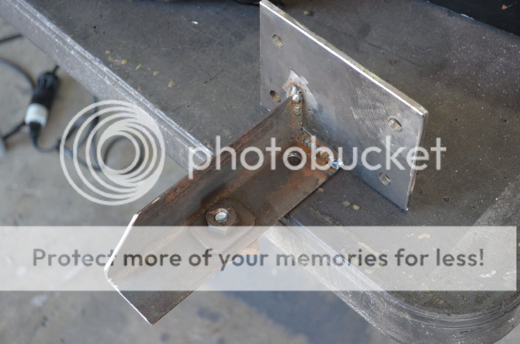
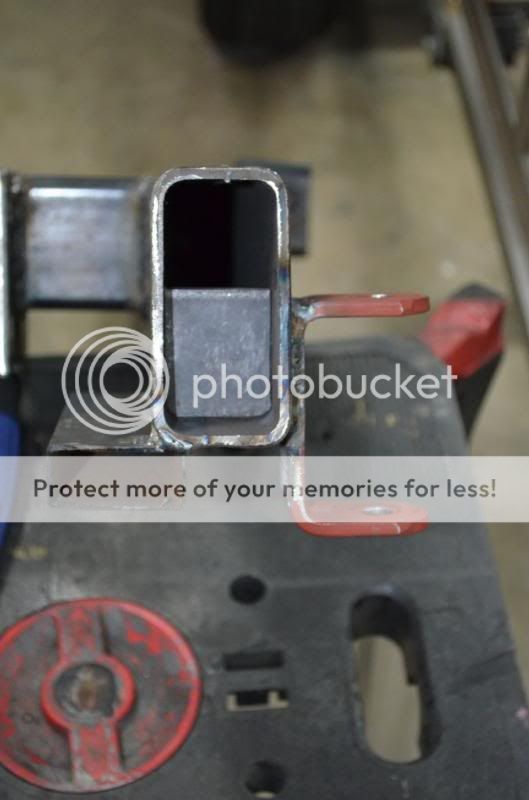
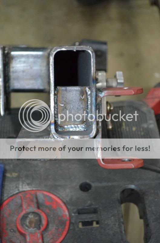
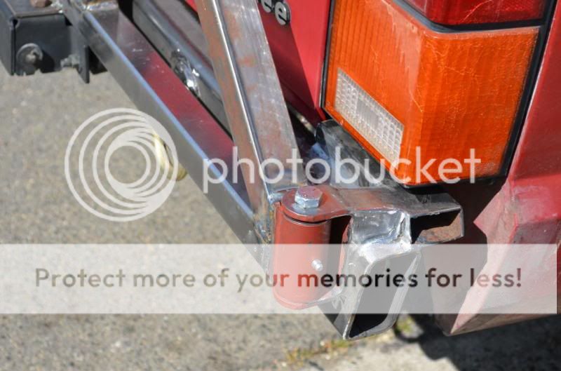
Also, to improve the towing strength and help support the overall weight of the bumper, I added a couple of lengths of 2x2x.25" angle iron to the inside area of the bumper mounting plates. These will have nuts welded onto them for bolting through from underneath.

RearBumper06.jpg


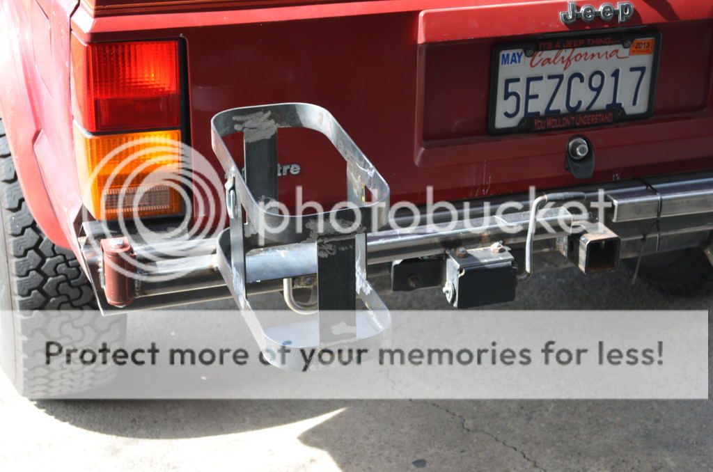
And because of the angle iron, the openings had to be enlarged:

RearBumper14-1.jpg


RearBumper15.jpg


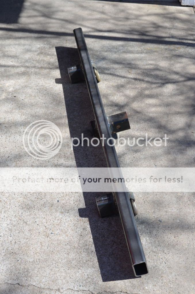
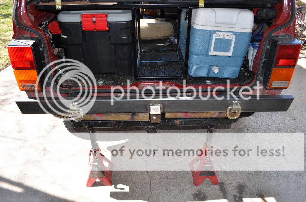
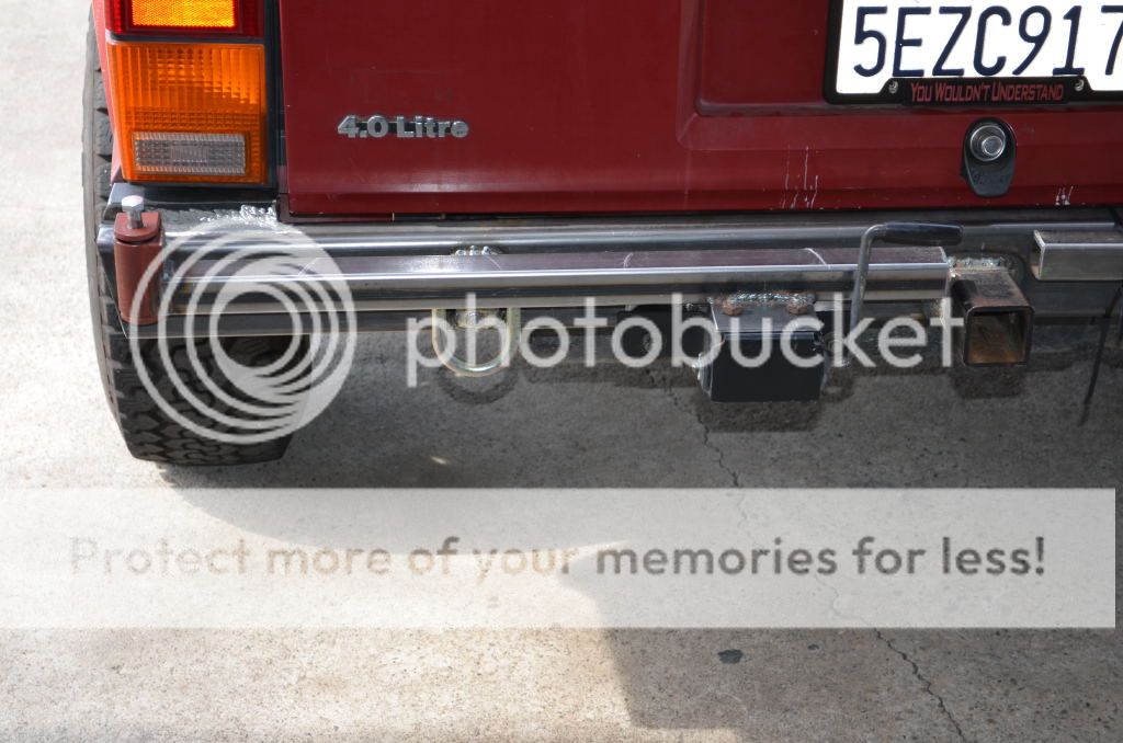
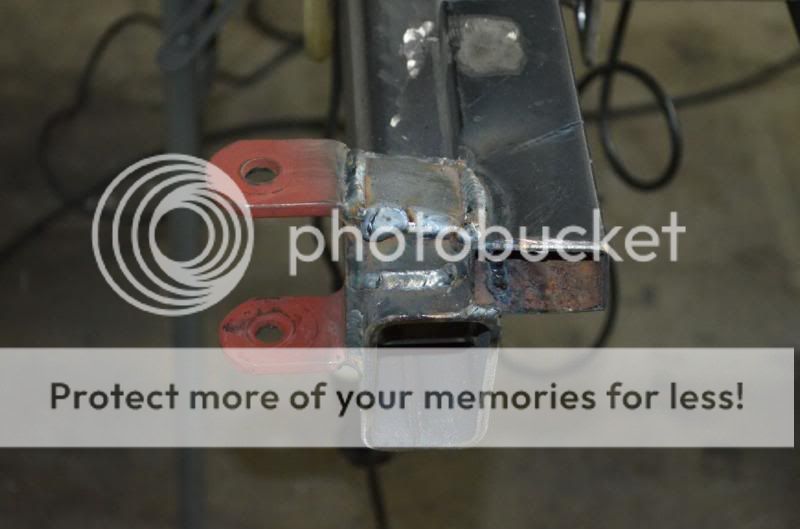
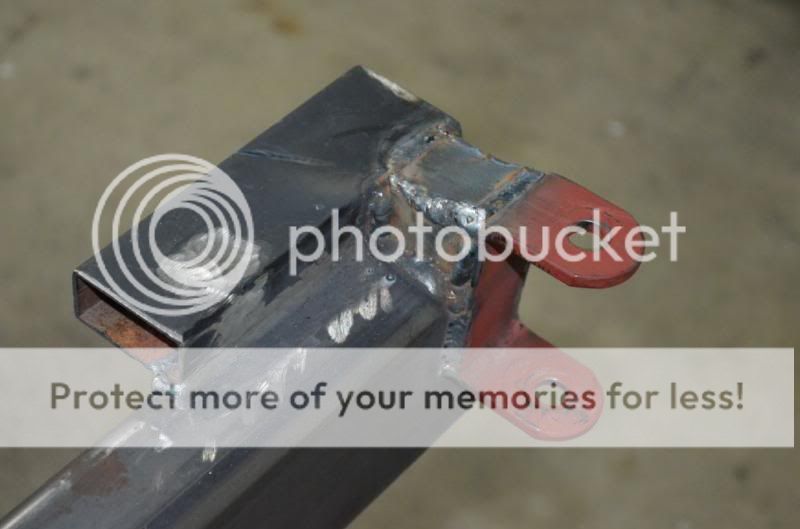
After bolting the mounting plates into place, the bumper was re-mocked into place and stand off measurements were taken, after the bumper bar was sitting where I wanted and where is looked the best.

RearBumper16.jpg


RearBumper19.jpg


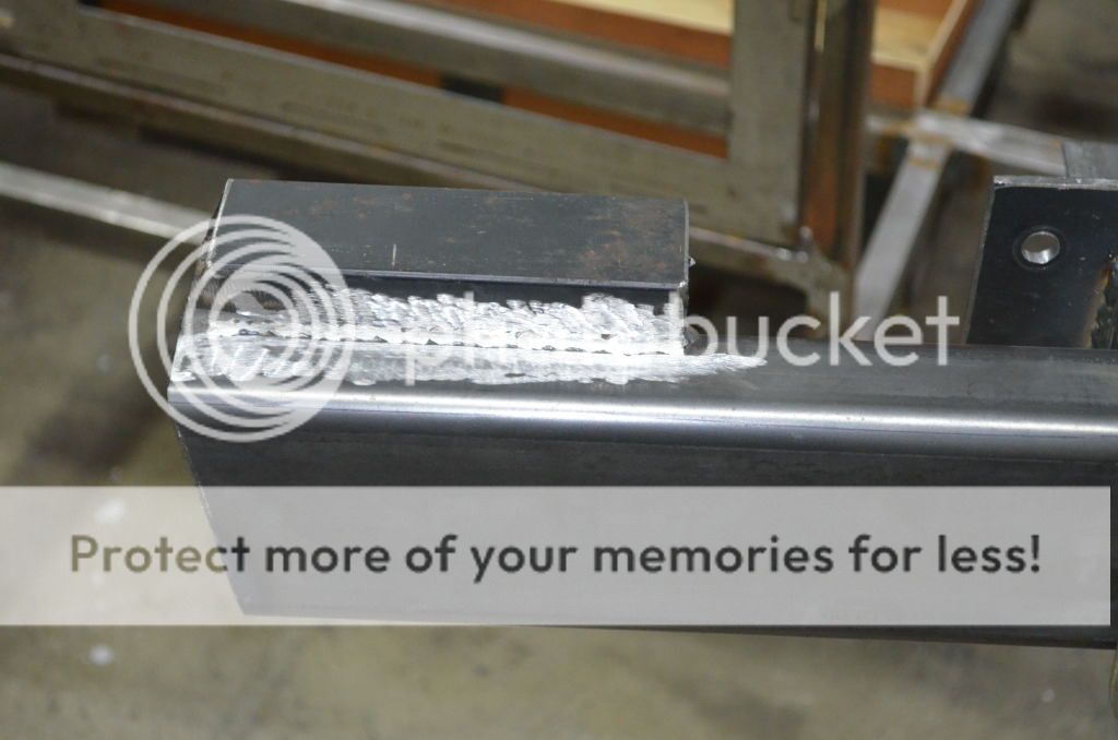
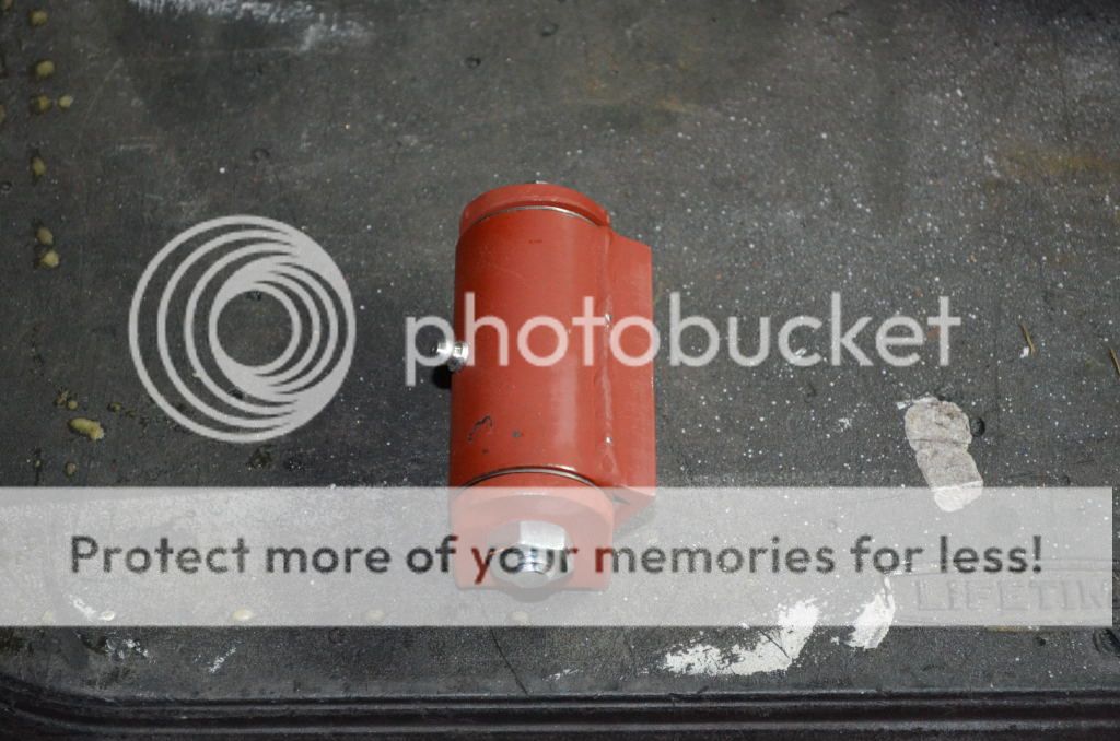
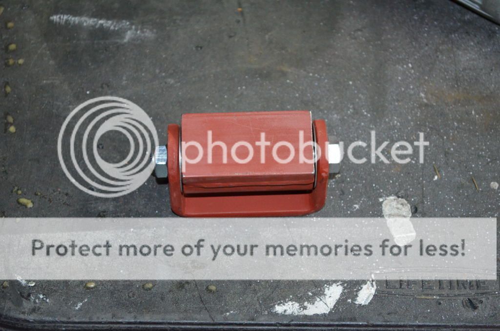
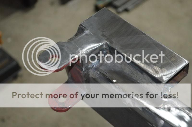
For the standoffs, I used 2x3x.25 rec tubing cut to 3" long.

More photos later.
 
You may have noticed the notch in the bottom of the bumper bar! That is for the trailer kitch receiver.

RearBumper36.jpg


RearBumper21.jpg


As for the bumper brackets: A couple of holes are marked and drilled from the underside to align with the bracket holes.


RearBumper37.jpg


Then a pair of body nuts are attached to the top of the bumper bracket angle iron.

RearBumper38.jpg
 
The nuts are used on F-350's to hold the body to the frame. We have to replace these things on a regular basis, as when doing any kind of engine work pretty much requires pulling the cab of the truck off the frame.

Here are both of the mounting plates with the nuts welded in:

RearBumper39.jpg


I also welded on a couple of D-rings (Harbor Freight) that are supposed to be rated at 11K pounds. (yeah, right!). They are welded in directly across from the standoffs for the mounting plates.

RearBumper40.jpg


RearBumper41.jpg


And, of course, you can see the trailer hitch receiver welded in.
 
Placed into position for a trial fit, just to make sure that nothing hasn't moved:

RearBumper42.jpg


RearBumper44.jpg


And added a couple of peices of tube that I had laying around as filler between the bumper and the taillamps:

RearBumper46.jpg


And to give everyone an ides of what the back side of the bumper is looking like:

RearBumper47.jpg


RearBumper48.jpg


It is here that I am departing from the normal rear bumper build. Instead of using a single hinge point, I wanted the rear tire rack / fuel can rack to split in the middle and hinge on each side. A couple of reasons. A) the shorter hinged arm = less torque and stress on the hinge. B) by mounting the fuel can on a hinged rack on the drivers side means that I can move fuel from the can to the tank with a simple siphon hose.

As for the hinges, I found a couple of gate hinges that are rated at 1000 pounds for under $100 for the pair.

RearBumperRacks01.jpg


RearBumperRacks02.jpg


They are weld on, sealed, greasable and have roller bearings with cages internally.

Passenger side welded on:

RearBumperRacks03.jpg


RearBumperRacks04.jpg


And with the arm welded on and mounted to the bumper bracket:

RearBumperRacks06.jpg
 
As for the latch to hold the swing arm, I poked around Pick-n-Pull for a considerable amount of time looking for what could be an answer. I didn't want to use the lock down bolt that a lot of diy bumper kits have, and I didn't want to use the over center latch. (that works great with one arm, but with two, not so good).
What I found was off of a Nissian Pathfinder. The latch is a nice unit that looked like it would be mountable in non-Nissian applications.

This is the drivers side:

RearBumperRacks08.jpg


And this is the intended use for the drivers side:

RearBumperRacks07.jpg


The large white thing is a water container that has pretty good insulation. It is a US Military spec peice of equipment that I picked up from a surplus place in town. We have used it a couple of times and there is still ice in the cooler at the end of the weekend.

The water cooler, I haven't made a rack for, as yet. But I did get some flat stock bent up to hold the Jerry Can:

RearBumperRacks09.jpg
 
Looks good. Have you thought about possibly welding a bracket/apparatus to keep the arms from swinging too far out? Not totally necessary, but would make a nice touch/less chance of damage of anything.
 
Looks good. Have you thought about possibly welding a bracket/apparatus to keep the arms from swinging too far out? Not totally necessary, but would make a nice touch/less chance of damage of anything.

Its funny that you should mention that. I took the truck to work yesturday and while demonstrating the bumper rack, the fuel can side swung out too far and hit the fuel door. No damage, but it did make me plan to put some bumpers in to keep them from over swinnging.

Good catch though!
 
Don't forget to add a hourly opener on the bumper/carrier somewhere. Everyone seems to forget that. Ha
 
Re: Re: Introducing Little Orphan Annie and Myself

Don't forget to add a hourly opener on the bumper/carrier somewhere. Everyone seems to forget that. Ha

I'm guessing "hourly" is supposed to be "beer" or "bottle" haha
 
Bottle Opener!? How the Hell did I forget that?! I am going to add that to my to-do list!

As for this update, this is what I had delivered to the shop last week:

NewTires02.jpg


NewTires03.jpg


And mounted the spare for fitting to the bumper rack:

NewTires01.jpg


The tires? GoodYear Dura-trac's 33x12.5x15.
 
Last edited:
Back to the bumper. I wanted to reduce the flex at the hinge mounting points. Added a small peice of steel plate inside the bumper tube between the hinge and the back wall.

RearBumperRacks23.jpg


And welded in.

RearBumperRacks24.jpg


Also boxed in the hinge arms on both sides.

RearBumperRacks25.jpg


RearBumperRacks26.jpg


Then ground the welds down.

RearBumperRacks27.jpg


RearBumperRacks28.jpg
 
thing is freaking awsome!!!!! i suppose i should start my build thread soon. any chance of you trimming fenders soon??? love everything you have done! fill the oil and check the gas!
 
A little update on Annie:

Welded on some end plates and filled the openings in the bumper. Right now it is sitting in the garage waiting for the first layer of paint to dry. It should be fully painted by the end of the weekend.
Sadly, I forgot to take photos of the end plates. :doh:

Here are a couple of better shots of what she looked like just before I pulled the bumper back off:

CherokeeStage403.jpg


CherokeeStage401.jpg


I think that I will start the wiring mods while I am painting the bumper and tire rack.
 
The Bumper is finished (yeah right). Here are some shots of how I cleaned up the ends:

RearBumperDone4.jpg

RearBumperDone1.jpg


The End Caps were made from 1/8" Steel Plate.

RearBumperDone3.jpg

RearBumperDone2.jpg


And what it looks like with the Camo Paint started on the rear;

RearBumperDone5.jpg
 
And the rack for the drivers side now includes a Cooler Rack. Built to hold a Igloo Cooler that is a pretty good copy of a Coleman Old School Cooler. And solves the bottle opener problem:

CoolerRack01.jpg


CoolerRack02.jpg


CoolerRack03.jpg


CoolerRack04.jpg


And what the system looks like with the Tire Rack Mounted and closed:

CoolerRack05.jpg


CoolerRack06.jpg
 
So, I mentioned that I was going to do a little wiring modifications on Annie. What I am doing is putting a '97 power distribution box in her.


The idea is to get rid of the relays (mounted to the right inner fender) and loose the fusible links (replacing them with real fuses)

And replacing that setup with something that gives me more then double to relay options and a bunch of easily diagnosible and replaceable blade fuses.


Here you can see that I have most of the wiring exposed and the PD partially wired in.


The best thing about doing this is that I have found one of my problems and the reason that it is very important and useful to relay and re-wire the headlamps.


I had installed a set of Hella' replacement headlamps with some pretty decent uprated bulbs. However, I was very disappointed with the results. The lamps were much dimmer then they should have been. I have done this on other vehicles prior and was expecting better results.
While pulling the wiring apart, I did find the cause and the reason to rewire your headlamps on your own XJ.

There is a connector located just behind the left side (drivers side) headlamp for the subharness for the front lights.
This is what my connector looked like!


The connector just crumbled when I disconnected it and the amount of corrosion inside the connector was impressive. I am certain that had I put a DVOM on the headlamp, I would have only seen about 9 volts.
 
I would recommend a DIY/aftermarket headlight harness anyways. Larger wires+ relays > stock wiring. Yes, the other lights work from that harness as well, but do not supper as much from the lower voltage.

Is that cooler going to be alright, loaded with beer and stuff, mounted that high up while wheeling and such? And what IF the cooler is not there, where the will bottle opener be?! Ha.

Keep up the good work. Wish I had the time/energy/motivation and all the equipment to do all the things I want to do.
 
Back
Top