compcrasher86
NAXJA Forum User
- Location
- Mass
Heres a nice little tutorial for those with 98's, I just did mine:
I decided not to make the splice right at the ECU just because it was kinda far from my switch, I wanted the shortest wire run, and I wanted it to be protected from the elements. So I pulled off the connector and confirmed pin A12 on the black connector. Then farther up the wiring harness, near the master brake cylinder area I picked through the harness in the split loom and found the "solid grey wire" everybody seemed to have. So I then shaved a bit of the insulation off with a razor knife and using a multimeter, confirmed it had continuity with pin A12. Be careful, there are plenty of grey wires in there with stripes, you don't want those!
(Just a little side note, I did trace the grey wire till it ended, and it ends in a wiring harness connector over by the distributor cap. There is a little plastic blocker over the other side of the connector that essentially caps the wire off. Police packages probably had a different wiring harness that had the grey wire on the other side of that connector and brought it into the dash. I chose over by the master cylinder because thats the closest accessible area to get through the firewall)
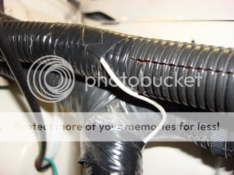
Then I cut the wire, and soldered my new extension wire in (I kept with grey just for color coding purposes), slipped a piece of heatshrink over, and re soldered the original wires back together. Slipped the heatshrink over and used a heatgun to seal it
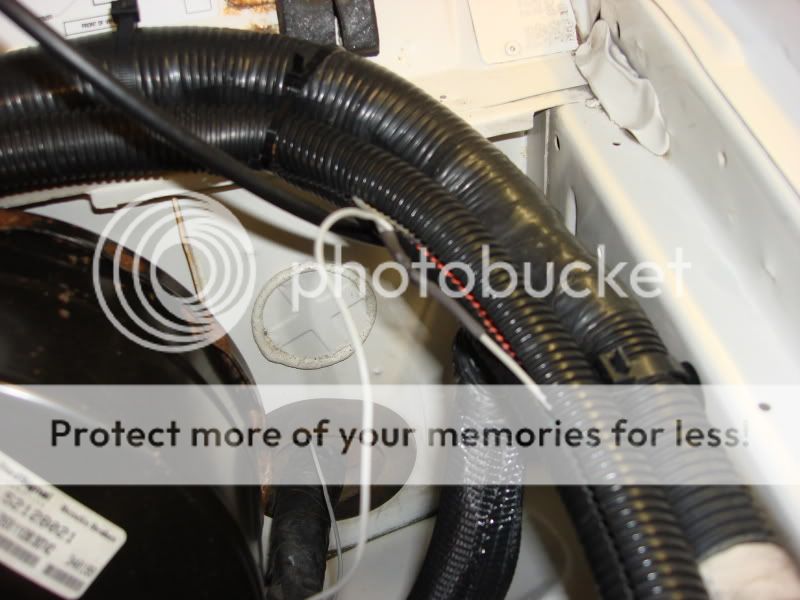
Then I ran it along an adjacent wiring harness and through the rubber boot through the firewall by poking a hole and threading it through with a coathanger. This was by far the most time consuming part because the rubber boot was a PITA to pierce. I then popped the wire into the split loom and taped wherever it was loose. This shows where the wire crosses from the ECU harness over to the one that goes into the rubber boot in the firewall
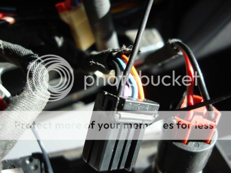
For my ground I popped open the connector for the factory fogs and soldered a thin black wire to the gnd for the fog switch, popped the connector back together and voila
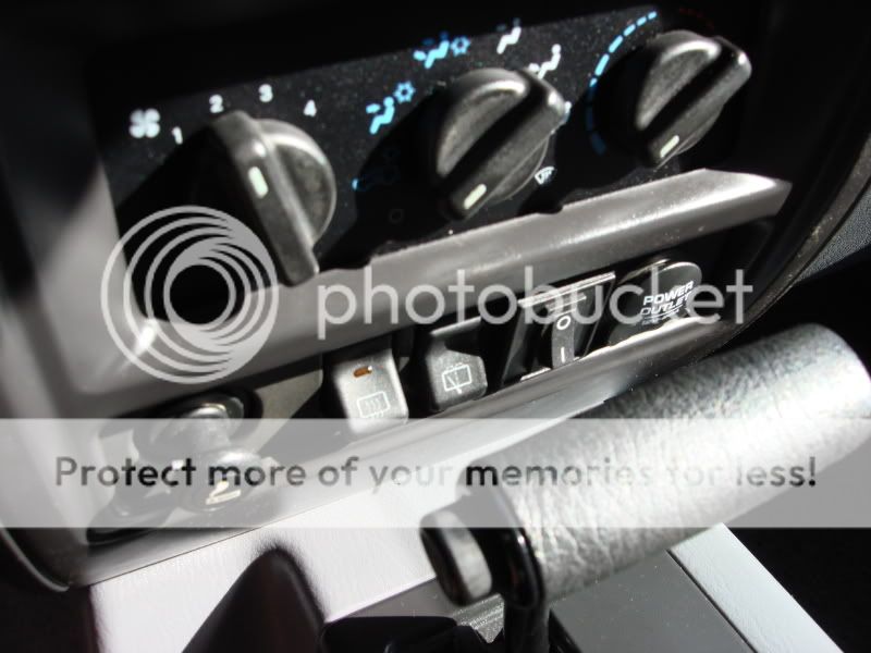
I cut out a piece of the factory blank and am using this temporary switch until I can bring myself to buy the factory one
Overall the job is invisible because the wires are well hidden and bound up, the connections were made well and waterproofed under the hood, and my extended idle switch works GREAT. Bumps it up to 1100/1200 rpm for me. I don't know how often I'll be using this but when I have to do a jump start or in hot situations, this switch will DEFINATELY be worth it
I decided not to make the splice right at the ECU just because it was kinda far from my switch, I wanted the shortest wire run, and I wanted it to be protected from the elements. So I pulled off the connector and confirmed pin A12 on the black connector. Then farther up the wiring harness, near the master brake cylinder area I picked through the harness in the split loom and found the "solid grey wire" everybody seemed to have. So I then shaved a bit of the insulation off with a razor knife and using a multimeter, confirmed it had continuity with pin A12. Be careful, there are plenty of grey wires in there with stripes, you don't want those!
(Just a little side note, I did trace the grey wire till it ended, and it ends in a wiring harness connector over by the distributor cap. There is a little plastic blocker over the other side of the connector that essentially caps the wire off. Police packages probably had a different wiring harness that had the grey wire on the other side of that connector and brought it into the dash. I chose over by the master cylinder because thats the closest accessible area to get through the firewall)
Then I cut the wire, and soldered my new extension wire in (I kept with grey just for color coding purposes), slipped a piece of heatshrink over, and re soldered the original wires back together. Slipped the heatshrink over and used a heatgun to seal it
Then I ran it along an adjacent wiring harness and through the rubber boot through the firewall by poking a hole and threading it through with a coathanger. This was by far the most time consuming part because the rubber boot was a PITA to pierce. I then popped the wire into the split loom and taped wherever it was loose. This shows where the wire crosses from the ECU harness over to the one that goes into the rubber boot in the firewall
For my ground I popped open the connector for the factory fogs and soldered a thin black wire to the gnd for the fog switch, popped the connector back together and voila
I cut out a piece of the factory blank and am using this temporary switch until I can bring myself to buy the factory one
Overall the job is invisible because the wires are well hidden and bound up, the connections were made well and waterproofed under the hood, and my extended idle switch works GREAT. Bumps it up to 1100/1200 rpm for me. I don't know how often I'll be using this but when I have to do a jump start or in hot situations, this switch will DEFINATELY be worth it


