• Welcome to the new NAXJA Forum! If your password does not work, please use "Forgot your password?" link on the log-in page. Please feel free to reach out to [email protected] if we can provide any assistance.

98 SE 5.3 Swap and Other Stuff

Well I came across a mistake I made yesterday. I put the manifolds in and they fit fine, plenty of clearance. Then proceeded to build the motor mounts without checking fit on the manifolds at all. Passenger side hit the motor mount so I had to notch the mount down about 3/4" and about 2.5" wide. I cut out a chunk with the plasma and used a piece of pipe cut in half and spread out to fill the gap. Oops...

sm134_zpsjrs4nzrc.jpg

sm135_zpsyjwr6unq.jpg

sm136_zpsflrhsy2a.jpg

sm137_zpsxr4b7iax.jpg


More this weekend hopefully-
 
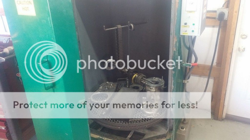
Looking good. I made my own motor mounts too, it's nice to put the motor where you want it instead of where Novak thinks it should be.

Thanks for the reply John. I have referred to your pics more times than I can count. In fact I just looked at them yesterday to see how you routed your exhaust.

I sincerely appreciate all the help you have given during my planning stages.

More to come this weekend...
 
Since I have been working on wiring I thought I'd show my gauge cluster. I actually built this last fall before I even bought my motor/trans. I decided to go with Intelitronix segmented LED gauges for a couple reasons. I wanted to do something a little different and I didn't want to spend the money for Autometers.

A few words about Intellitronix. Definitely cool gauges but the whole ordeal was a huge pain in the ass. I ordered my gauges from their eBay store. When they showed up some of the LEDs had varying brightness and the OIL gauge lettering below the numbers was crooked. I emailed the company and sent the gauge back on my dime. It took about 6 weeks to get a gauge back from them. Then I noticed some of the other gauges were not right so I called and talked to a gal there. Long story short it took 7 different shipments of gauges and nearly 2 more months to get all the gauges I needed with the correct color, correct lens tint etc... Their QC absolutely sucks donkey nuts. They are Made in Murica and have a lifetime warranty on them though.... /rant

I modified the plastic surround so I could fit the entire large gauge bezels inside the cluster. I went to a local plastic outfit and asked for glue that I could use on the surround and since it is made from Polypropylene nothing will stick to it. So I cut the surround apart and then used a soldering iron to "weld" it back together. I made a backing piece from .090 5052 aluminum sheet and then covered it with some carbon fiber vinyl for some bling. LED indicators are from Amazon and I got my CEL from Painless I think.

I used a 35 pin connector I got from Digikey for the wiring. I used 32 of the 35 pins. Then made a small enclosure for the connector out of some .035 aluminum sheet.

Anyway... Pics:

sm-20150811_221506_zpsi4xrxylf.png

sm-20150815_155145_zpsqpgfrniq.png

sm-20150815_171441_zpsr4x8ca2r.png

sm-20150819_205441_zpszusnopl9.png

sm-20150819_205422_zpsccdxkj8g.png

sm-20150819_205409_zpsmnkesorw.png

sm-20150818_102937_zpsokt8koqs.png

sm-20150821_142708_zpsevukakxv.png

sm006_zpsch0wcjnv.jpg

sm008_zpsgbfy9fot.jpg

sm010_zps22p4xtq6.jpg

sm-20150822_140550_zpsvmkx7h3l.png

sm001_zps4tlg7uwr.jpg
 
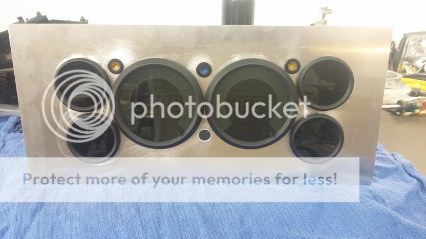
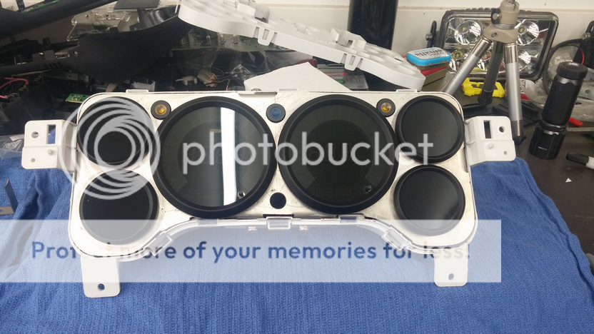
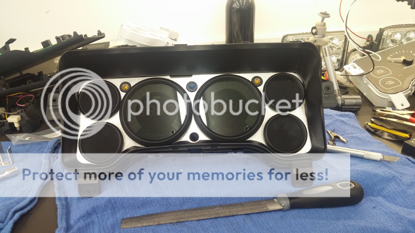
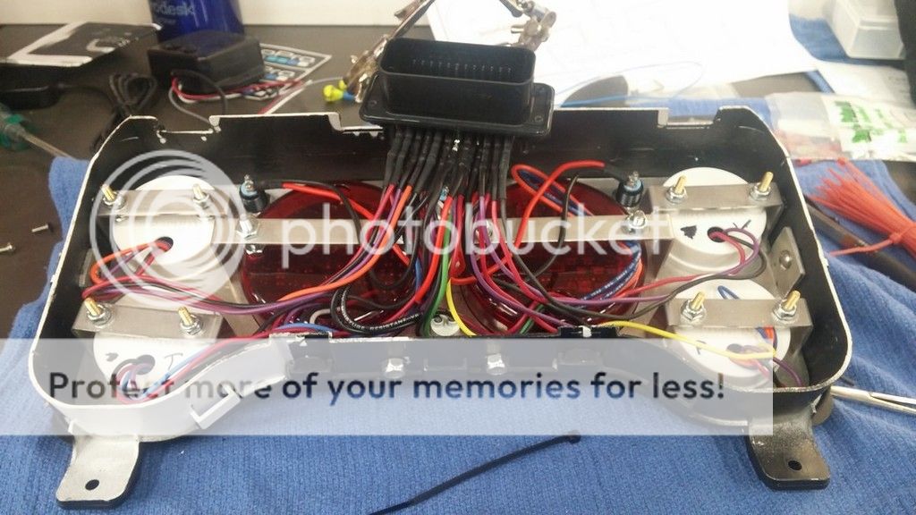
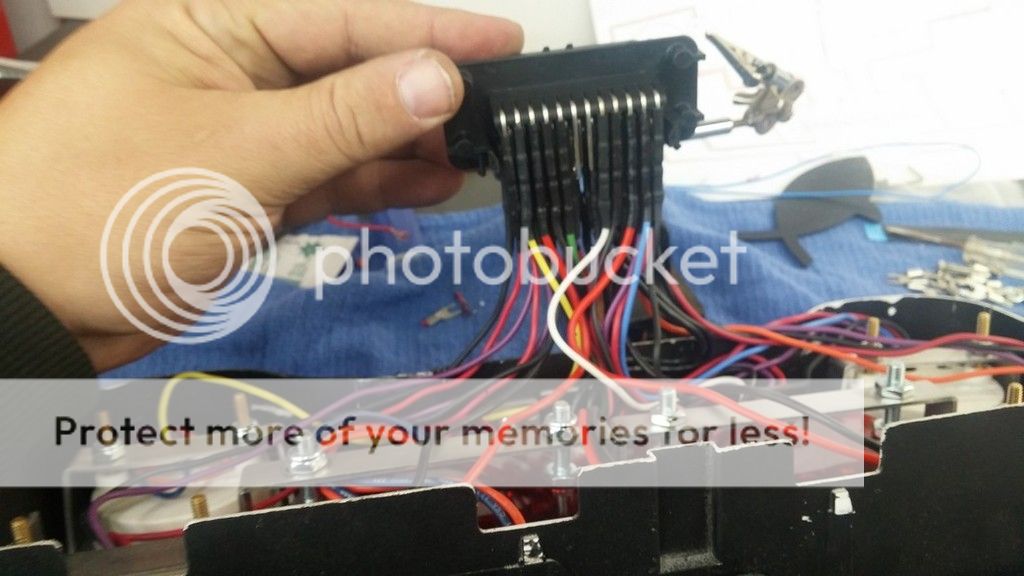
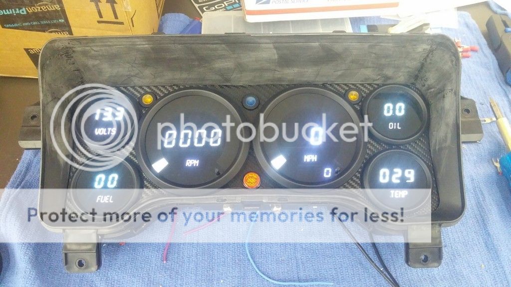
Even though I'm not a fan of digital gauges, this does look nice. And what you did here with the connector is awesome, about a million times better than the back of mine.

Thanks John. These gauges are neat but really the only reason I went this way is the price. They were less than half the price of Autometers but I like the look of Autometers a lot more for sure. If I end up wanting to switch them out later on it will be a lot easier with the connector setup. I'll give them a try and see. One of the incorrect shipments Intellitronix sent me was actually a set of RED LED gauges and Those looked better than the white. Kinda wish I would have gone with red instead...
 
Photobucket must be having issues. When I log in nothing in my entire account is visible and a bunch of photobucket icons on the website are missing too.
 
Ok I'm still working out some wiring and I can't tell what is going on. Hopefully someone can help.

I have everything hooked up from the PCM to the Jeep side, however I am not getting any voltage for the fuel pump trigger wire which is pin 9 on the green connector. I have double checked all of my grounds and power wires and they all seem to be hooked up correctly.

Also when I key on the throttle body just rapidly clicks and the pedal does nothing.

I have plenty of voltage in the battery. Below is the schematic I drew up when hooking all this stuff up which shouldn't have anything to do with the no voltage problem at the PCM

Any ideas guys?

wiring_zpsqiozuvto.png
 
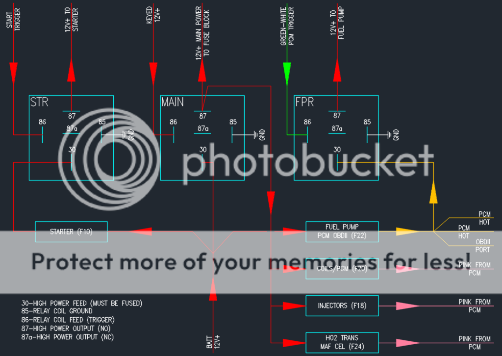
Pin 9 Green says it's a control signal. Put it on the ground side of your relay and it should work.

Thanks for the reply John... However according to everything I am reading pin 9 should supply +12v for a couple seconds at key on and then when it senses the crank signal turns it back on for starting. This is from LT1swap.com:

Fuel Pump Relay Control - The computer on GM fuel injection systems is designed to control a fuel pump relay. The computer does this by supply a 12v+ (POSITIVE) signal to the relay. The signal is only present for two seconds at key on. Fuel pump operation resumes when cranking over. The PCM ONLY commands it back on when the PCM reads that the engine is turning over. So, if there is a condition where there is a bad crank sensor, fuel pump will come on, turn off, and will not turn on when cranking.

I tested it both ways - as a ground and as a hot and I get nothing either way. I sent Brendan at LT1swap an email but he takes a long time to reply these days. Last email I sent him took 10 days to get a response...

I posted a question on ls1tech.com too but no replies there yet.
 
Thanks for the reply John... However according to everything I am reading pin 9 should supply +12v for a couple seconds at key on and then when it senses the crank signal turns it back on for starting. This is from LT1swap.com:


I tested it both ways - as a ground and as a hot and I get nothing either way. I sent Brendan at LT1swap an email but he takes a long time to reply these days. Last email I sent him took 10 days to get a response...

I posted a question on ls1tech.com too but no replies there yet.

If you're a member of Pirate check out the 5.3 swap thread in the Hardcore Jeep section. Post it up there and a lot of times Wayne replies who is the guy that does 150tunes.com
 
If you're a member of Pirate check out the 5.3 swap thread in the Hardcore Jeep section. Post it up there and a lot of times Wayne replies who is the guy that does 150tunes.com

Thanks PJ... I've read through that thread a couple times. Lots of good info but holy shit is it scattered around.

I have been doing more reading this morning on ls1tech and I am now thinking I have a grounding issue. I'm going to go over my grounds again later and redo my temporary connections to be more solid. I'll report back after I do that-
 
I'm an idiot.... I didn't have the ground for the TAC module hooked up. It was wrapped up with all the cruise control wires and apparently I forgot to label it. Pedal works and the fuel pump trigger works now... :cheers:
 
Did some work on the transfer case this weekend. I picked up a first gen S10 231 to get my input shaft and 6 pinion planetary. Just for reference I was reading a couple S10 forums and a few guys said that all of the original body style S10 231 cases (82-93) have 6 pinion planetaries and wide chains. The downside is its the old style gear cut so it may be a little louder than the newer style. Everything I have read says the gear cut changeover year is 94 so if you are using the older style like me grab a 93 or older case or 95 or newer if you are using the newer cut.

Below is a comparison pic of the 3 different input shafts I have come across. Far left is the 27 spline input, wide bearing (BD50-8), 6 pinion planetary out of the S10 case. Middle is the 23 spline input, narrow bearing, 3 pinion planetary out of my original 98 case. Far right is the 23 spline input, wide bearing, 3 pinion planetary out of the 93 case I picked up this past weekend.

sm148_zpsgt39moxk.jpg


These next couple pics are of the difference in gear cut in the planetary pinion gears. you can see the older pre 94 cut has a wider crown on the teeth vs the post 94 narrow crown.

sm149_zpsfpqhznck.jpg

sm150_zpsz09ilxqv.jpg


Getting the needle bearings out of the rear of the case is a pain in the ass. I used a Dremel and a few sanding drums to sand down the outer race until it split and I could knock it out with a small slide hammer.

sm152_zpsyc9x7hpz.jpg


I'm pretty fortunate to have a good friend that rebuilds transmissions at home as a side business so I called him up and took all my parts out to his hot wash tank.

sm153_zpsvx776frh.jpg


All the clean parts ready to drop in the case. I had to order a couple more bearings and one seal which should be here by the middle of the week and then the case can be final assembled.

sm154_zps6fyoynkl.jpg


This is a pic of the OEM shift comb vs the 2 low comb that came with the kit I bought several years ago from DC4WD.

sm155_zpsw35onqyt.jpg


And this is a screen shot of the adapter ring I need to make. It is very similar to FrankZ's adapter plate he made. I haven't decided if I want to make it out of aluminum or steel yet. Any opinions on that?

231%20adapter%20screen_zpsjgfolsmm.png


Here are some shots of me machining my custom tail shaft housing
sm139_zpsndyxht0h.jpg

sm138_zpsur2aamyk.jpg

sm141_zps8mobm8r0.jpg

sm143_zpsdy9rul2r.jpg

sm144_zps6ibtctp3.jpg

sm146_zpshcay3zer.jpg


I uploaded another video to my channel showing the custom tail shaft work I am doing on this case as well. Check it out if you want: https://www.youtube.com/watch?v=LIXx4JCMO5Q

More later this week.
-Jess
 
Back
Top