• Welcome to the new NAXJA Forum! If your password does not work, please use "Forgot your password?" link on the log-in page. Please feel free to reach out to [email protected] if we can provide any assistance.

98 aw4 tc lockup switch

Well, a great number of the under-hood connectors in an XJ (at least, the late model ones) are from the FCI APEX 2.8mm series. Haven't figured out which ones yet, but most of the ones with the little red plastic safety latch on the retention clip are.

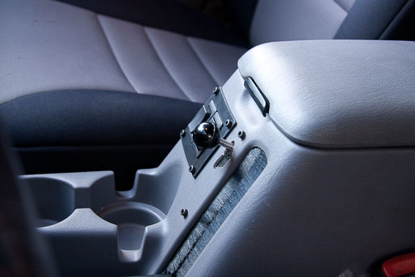
What I'm doing for this test is splicing about 6 feet of good quality wire to each side of the connector for the transmission (the one right by the dipstick tube that isn't the NSS connector.) I'm running the cable into the passenger compartment via one of the holes in the firewall to a barrier strip mounted on a piece of plexiglass that sits in the passenger seat. That way I can wire test hardware to the barrier strip and drive around without worrying about sealing the whole thing up, and can take live measurements. For this test I actually could do the same thing but put the wiring in between the TCU (under the dash by the gas pedal) and the wiring harness, but I hate trying to get under there and wire is cheap.
 
That makes sense. Sounds like we're closing in on it. We just need to drill down on the resistor values and then test them out on multiple vehicles for validation.

I really need to shop for some quality automotive connectors/plugs. I would have accomplished a lot more last night if I hadn't been fighting so many bad connections, alligator clips, and messy, tangled wires. :rolleyes:

Any suggestions for quality automotive plugs/connectors? What does everyone else use?

Look at Waytek for connectors and wiring supplies.
 
EDIT: I am an idiot and cannot read

Also, Terminal Supply Co frequently has stuff you can use on an XJ.
 
Time to resurrect this...

I tested my ideas and long story short, it worked. A 330 ohm resistor from each TCU solenoid drive line to a good ground will fool the TCU perfectly. I drove about ten miles including both city and highway driving (up to 90mph) and it functioned exactly as I expected. No CEL. The only thing you have to be careful of is that you leave the output and (if equipped, 98-up only) input speed sensors wired to the TCU. PS, there was some question as to whether the TCU would compare the input and output speed sensor signals and the gear it expected to be in and flag a malfunction if it didn't agree, but I saw no evidence of this while driving it.

I have not tested the higher resistances I considered and may not bother, since I can't find them in my parts bin (I hate moving!)

And I don't think I'm ever going to get used to driving a normal AW-4 setup again, on my way to work in the MJ today I found myself wanting to shift differently from what the TCU was doing. Guess I'll have to set all my jeeps up with this now :dunno:

So all you need is 3 (or 2, if you only want to control shifting and don't care about the torque converter lock, or even only 1 if you just want to be able to force 1st vs 2nd gear while in 1-2) 330 ohm, 2 watt power resistors. Then you can use whatever "manumatic" shift switch setup you want - RADesigns, Montana Fab (which includes the resistor setup), homebuilt, etc.
 
OK, I was finally able to get some quality time in the garage this weekend, and resumed testing. I discovered that my test rig was riddled with bad connections. Too many alligator clips in a rat's nest of wires. It retrospect, it's a small wonder it ever worked at all. In an effort to clean up the mess, I cobbled together a small circuit board (my first!) to hold the relays and provide reliable connection points for the resistors (so I could swap out values for testing) and all the wires from the tranny, TCM, switches, and shifter. All in all, it's 12 wires and 3 resistors connected to the board.

IMG_7480.jpg
IMG_7486.jpg


IMG_7487.jpg


Testing revealed that 1k-ohm 1W resistors are sufficient, and that means the current draw is reduced to the point where the resistors don't even get warm during use (less than 0.2W being dissipated) -- a significant improvement over the big 12 Ohm resistors that got too hot to touch.

Here's the board with the resistors. I may just leave it as is rather than making a whole new board just to solder them in place. It would look better, but it wouldn't perform any better, and no one's ever going to see it again anyway. And this allows me to easily swap out resistors in the future should long-term testing reveal the need.

IMG_7488.jpg


And here's the final installation. It works great -- I've driven it for about an hour total (over several short trips), switching back and forth between the manual shifter and the TCM with no ill effects and no CEL. The torque converter can be independently locked, unlocked, or controlled automatically by the TCM also with no ill effects and no CEL.

IMG_7491.jpg


IMG_7493.jpg


IMG_7495.jpg


All in all, I couldn't be more pleased with the results so far. The real test will come in a few weeks when we head to the Rockies for some testing on the trail.

Incidentally, the schematic I posted earlier has an error in it. I don't seem to be able to edit that post (because it was too long ago?), so here is the corrected version which also has the resistor values updated.

Shifter%20Schematic%20v3.gif
 
Perfect timing, kastein! Looks like our results are similar. That's great news, as it gives me even greater confidence that this will work permanently. Can't wait to try it on the trail.
 
Wow, that was a heck of a coincidence... nice first shot at a PCB by the way, my first was done at around age 12 with the "sharpie method" and came out terribly :roflmao: did you use toner transfer or the radio shack dry transfer patterns?
 
Wow, that was a heck of a coincidence... nice first shot at a PCB by the way, my first was done at around age 12 with the "sharpie method" and came out terribly :roflmao: did you use toner transfer or the radio shack dry transfer patterns?

Yeah now that you mention it, I think I tried that once too. It was a disaster. I guess this was my first successful one. Certainly not pretty, but it seems to work.

I used the toner transfer method. Printed the artwork on a page cut from an old magazine. The first attempt failed because I didn't clean the copper board good enough first. So, I scrubbed it off, got it clean, and tried again on the same board. Worked perfectly. Frankly, I was stunned.
 
Pretty neat, isn't it?

I do that occasionally when I'm short on time and need a PCB done by tomorrow and it's 11pm, and sometimes have a friend of mine with a CNC mill do them using that and a really really tiny end mill, but generally I have my boards done by barebonespcb.com or 33each.com / 4pcb.com (all the same company, just different bargains they offer) depending on what kind of requirements I have. I use CADSoft EAGLE for design, it's got a really strange user interface to get used to but once you learn it pretty well you can really fly.

The Radio Shack dry transfers are GREAT, but you have to do the design directly on the PCB, by hand, with an x-acto for edits. It's a bit tedious if you are doing more than one board but results in far better trace quality than (most) toner transfer methods will produce.

Also look into cupric chloride PCB etching if you're going to do more than a couple, it's way better than ferric chloride.
 
Pretty neat, isn't it?

Indeed. Those feeble gears in my head are already turning through the possibilities...

I do that occasionally when I'm short on time and need a PCB done by tomorrow and it's 11pm, and sometimes have a friend of mine with a CNC mill do them using that and a really really tiny end mill, but generally I have my boards done by barebonespcb.com or 33each.com / 4pcb.com (all the same company, just different bargains they offer) depending on what kind of requirements I have. I use CADSoft EAGLE for design, it's got a really strange user interface to get used to but once you learn it pretty well you can really fly.

The Radio Shack dry transfers are GREAT, but you have to do the design directly on the PCB, by hand, with an x-acto for edits. It's a bit tedious if you are doing more than one board but results in far better trace quality than (most) toner transfer methods will produce.

Also look into cupric chloride PCB etching if you're going to do more than a couple, it's way better than ferric chloride.

Great tips! Thanks. :thumbup:
 
I'm also considering a shorter shaft on the shifter. And possibly an alternate knob. The RADesigns shifter is nice, but it does tend to bind/stick if you don't grab it closer to the base of the shaft.
 
in the interest of full disclosure, I had a CEL last night while driving in town. Code was P0751, which comes up as a shift solenoid A (1-2 / 3-4) failure with some searching. I am fairly certain it was due to a sketchy connection* as I cleared it and it hasn't reoccurred in 30 more miles of city+highway driving, but figured I should post it.

* likely my ground for the dummy load resistors, since it's a ring terminal I jammed under a rusty bolt and tightened down with pliers :anon: didn't have my wrenches on hand and was lazy. It happened while I was driving at fairly low speed in a bumpy construction zone.

I'm going to clean up that ground and spend a few days driving it to/from work (it's my prototype rig, I usually drive the MJ everywhere) to make sure it was a fluke.
 
Hopefully it was just a loose connection. I was constantly fighting (and losing) that battle until I tightened up the connections and made the installation more permanent. Since then, I've had no CEL, but I've driven it less than an hour total. Time will tell...
 
Next up: A 2x16 character LCD display showing the real-time status of the transmission (Auto/Manual mode and current gear) and torque converter (Auto/Manual mode and Locked/Unlocked).

All of the necessary inputs look to be available from the TCM connector, with one exception: there is no way to distinguish Park from Neutral without adding a separate switch/sensor of some kind to the shifter mechanism. That should be simple enough.

Mockup:

LCDMockup.jpg
 
Yep, that's something I have planned for my build. I'm going to have a display that says what the TCU is trying to do (including TC state) as well as the state the transmission is actually in. I'm also probably going to wire mine up so it automatically unlocks the TC when I hit the brakes, and I'm looking at a few other things as well.
 
Strangeness. Drove to work yesterday in manual mode; very little shifting as traffic was light and it's mostly highway. Everything worked perfectly, but the CEL came on at about 15 miles. Naturally, I didn't have my scanner. CEL stayed on during a short drive to lunch in auto mode. Stayed on during the drive to Walgreens near my house, on the way home -- still in auto mode, trying to avoid setting additional codes. However, when restarting at Walgreens to go home, the CEL was off. Stayed off all the way home in auto mode. Checked codes this morning:

P0700: Transmission Control System Malfunction (Current)
P0751: Shift Solenoid A Performance or Stuck Off (Current)
P0756: Shift Solenoid B Performance or Stuck Off (Pending)

Cleared the codes, and drove to work this morning in an effort to duplicate the test; same route, same conditions, etc. Made it all the way to the office with no CEL. Brought my scanner along this time; checked codes:

P0751: Shift Solenoid A Performance or Stuck Off (Pending)

The TC switch was in auto mode for ALL of the drive time above which would explain why there we no TC-related codes.

Now what? Swap the 1k resistors for the 100-ohm ones? :dunno:

I think the TCM is looking at more than the presence/absence of a load on the solenoid driver outputs. I think it's smarter than we're giving it credit for. It's clearly smarter than me (which isn't saying much). In fact, I think it's toying with me. I'm pretty sure I heard it chuckle at me when the garage was really quiet last night... :eeks1:
 
I'm getting the same two codes - 751 and 756. I got 700 once, but figured it was an NSS flakiness issue or something.

I tend to get 751 and 756 while cruising at 25-40 miles per hour in town, generally accelerating or decelerating. I blamed it on a ground initially but I'm starting to think it's due to the TCU being smarter like you said, and comparing the ISS and OSS signal frequencies and determining that it didn't shift to the gear it wanted to...

This could get real interesting. Does anyone in the northeast (the closer to central mass, the better) have a '97 with the AW4 that they want to test? I have my test rig built in such a way that I can install it without doing any wiring harness modifications. My bet is that the '97 will not detect the tricks we're playing due to the fact that it does not have an ISS, just an OSS.

I still have not gotten a TC lockup solenoid code (let me know if you do, raneil, it'll be P0760 or P0761 most likely.) My bet is that this is because the TCU cannot (easily) determine that the TC is not locking due to the fact that it doesn't have easy access to the engine RPM reading to compare to the ISS reading, and on a 97, can't differentiate a TC lockup failure from a shift solenoid failure because there is no ISS.

My bet is that Montana Fab (who makes the best 1-2 override switch that I know of on the market today) doesn't have this issue because their switch is only designed to operate when the shifter is in the 1-2 position, and the TCU isn't checking things as carefully in that mode.

If the 98-up TCU is smarter than I expected and is determining whether the trans shifted or not via ISS/OSS values, this is going to require much more in-depth modifications to the TCU than I expected. Wouldn't be surprised if I have to reverse engineer and customize the firmware.
 
My bet is that Montana Fab (who makes the best 1-2 override switch that I know of on the market today) doesn't have this issue because their switch is only designed to operate when the shifter is in the 1-2 position, and the TCU isn't checking things as carefully in that mode.

My thoughts exactly. Or because the CEL only comes on if there is more than one error condition. I notice their unit doesn't allow control of the TC, either. It would be interesting to know if using their device sets a code internally, but doesn't light the CEL.

If the 98-up TCU is smarter than I expected and is determining whether the trans shifted or not via ISS/OSS values, this is going to require much more in-depth modifications to the TCU than I expected. Wouldn't be surprised if I have to reverse engineer and customize the firmware.

That's above my pay grade, but would almost certainly work if it could be done.

Taking a different approach, I wonder if it wouldn't be possible to simply take over the TCM's inputs rather than it's outputs. There are only three three of them. The two shaft speed inputs appear to be little more than 5V pulses whose frequencies directly correlate to shaft speeds. The TPS is a basic voltage divider with one resistor being variable, thus providing a voltage proportional to throttle position. So (theoretically) one could measure the appropriate pulse frequencies and TPS voltage for each forward gear. Programming a micro-controller to produce those signals on demand shouldn't be all that difficult. Smoothly switching between the real and the false inputs without upsetting the proverbial apple cart might be tricky though...

As long as the TCM is not comparing notes with the ECU regarding the values of those 3 inputs (which are also visible to the ECU), we should be able to lie to the TCM and let it do the shifting for us, no?

Admittedly, that's idle speculation on my part. I don't know that I'd go to that much trouble at this point. What I have now works more than well enough to suit my needs -- besides it's already installed and ready to go. Now that I've finally broken down and purchased a code scanner, I don't worry so much about an occasional CEL. And once the novelty wears off, I suspect I'll only use the manual shifter when I really want it for holding 1st or 2nd gear on the trail -- in which case I'll probably never see another CEL. Time will tell...
 
Back
Top