Vanimal
NAXJA Forum User
- Location
- escondido, ca
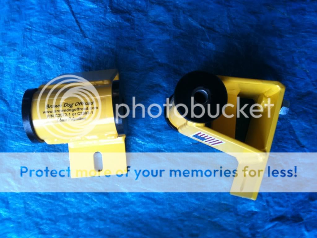
don't post your crap up if you're going to get butt hurt when you get an opinion. nobody said it was junk, we were just offering a suggestion.Yall are trippin. Just because there's room doesn't mean it needs a gusset. 1.5" square tube that stands less than 1.5" off the base, and it needs to be braced? Guess I should have machined it from a solid block. The stock block bracket will break first.
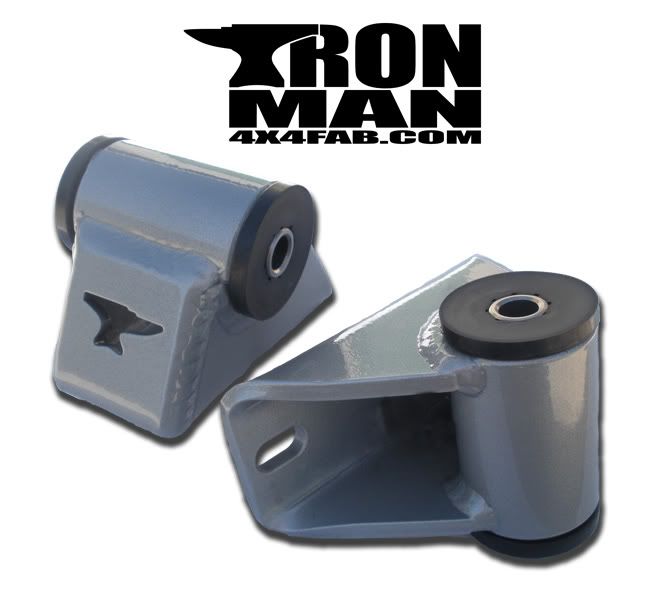
Quick, tell this guy his v8 is going to fall out the first time he starts it up:
http://www.naxja.org/forum/showpost.php?p=245598654&postcount=8
you're obviously new to fabricating, we are not.
Last edited: