• Welcome to the new NAXJA Forum! If your password does not work, please use "Forgot your password?" link on the log-in page. Please feel free to reach out to [email protected] if we can provide any assistance.

*NEW* 4-Link Long Arm Upgrade

Status
Not open for further replies.

redrider2911

NAXJA Forum User
Location
Yakima, WA
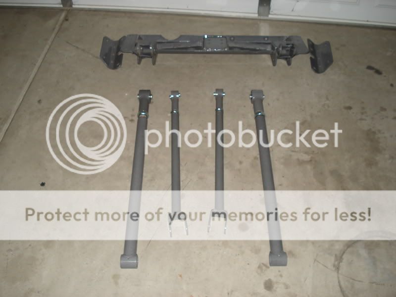
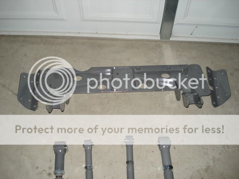
K guys, so after posting up my true 3-Link design I had alot of members asking about a true 4-Link. I got on the ball and realized I could use the same concept of the 3-link crossmember and just mirror the upper mount to the other side. There doesnt look to be any apparent clearance issues. Luckily is seems Snyder has volunteered his Jeep to do the first mock up of this kit. The lower links are going to be the same as the 3-link using 7/8s heims or the option of Ballistic's poly bushings at the axle end. On the upper link there will be a 7/8s heim on the frame mount and a "U" shaped adapter on the axle side that will bolt to the stock UCA mount at the diff and on the passenger side (or if you have the weaker sheet metal mount on a non-disco axle you can purchase a new one). The reason I call it an adapter, for lack of better term, is because unlike how most kits have a welded on "U" instead I have designed this piece with a threaded stud so that it will still thread into the UCA and act as a turn-buckle for adjustments. The only thing I can honestly say that I dont like about this kit is you have to drill absolutely strait through the frame rail to match the whole on the other side. This tends to be difficult because the frame rail isnt exactly square. If anybody has ideas for improvement on this aspect of the design feel free to chime in.

If you guys have any questions or thoughts feel free to let me know.
Thank you, Kris Froehlich of Froehlich Suspension Technology

K so on with the 3D Models.

4-link.jpg


4-Link3.jpg


4-link2.jpg
 
Beef up the mounts that the belly pan uses to attach to the uni body. They may work now but honestly 4 bolts on the uni rails doesn't seem like enough to me, even with the 4 or 6 threaded bolts into the unibody I would add at least one more through bolt on each side with sleeves.

-Alex
 
just a thought you did not post a shot of the bottom of the skid but it seems that the bolts would bear the brunt of any abuse. just a though maybe recess the bolt heads?
 
There are (2) 9/16 bolts with anti crush sleeves through the rails and control arm mounts on each side to take any stress from twisting caused by the torque from the axle through the arms. Then there are (3) M10 grade 12.9 socket head bolts up through the bottom of each frame rail using the stock weld nuts. These are honestly more for installation purposes and to keep things snug, these bolts will see very little stress. The crossmember and skid plate are attached to those mounts with (3) grade 8 bolts on each side. One more bolt then stock, a higher grade, bigger size, and through 1/4" plate. Not sheet metal and a weld nut. These bolts mainly just support the weight of the tranny and crossmember. I can assure you that there is no compromise on the design of the mounting and the amount of fasteners used. Everything is 1/4" plate, most other products you find on the market are 3/16" and none of them have means of attaching the new crossmember or UCA/LCA mounts of this degree.

You are correct, on this rendered image the studs from the tranny mount would hang below the crossmember. This is also something I have fixed in my new design since the 3-link but have only drawn it up in CAD so I could laser it out. Let me make the changes to this 3D model and post up the new image in a couple minutes.

Thank you for your questions,
Kris
 
You can see here that there is a raised section with slotted holes for the tranny mount. Under that is the plate from the crossmember with a 7/8s hole to fit the nuts and the socket through to tighten it down.

raisedmount.jpg


I hope this next pic will help explain how the control arm mounts tie into the uniframe.

mounting.jpg
 
Could you post a drawing showing the suspension cycling so we can see how the caster changes during movement? I ask as the crossmember mounts have little vertical displacement compared to the stock mounts. Or, have you compensated the offset horizontally?

Personnaly, I like the fact that you can remove the crossmember without disturbing the CAs. Most of the long arm kits require removing everything...
 
That is correct that idealy you would want more seperation at the frame but there is absolutely no more room. The Upper heim joint is about 1/8" away from the floor in this design. All though the stock arms have a little more seperation, they are different length which does mess with proper geometry and suspension cycling. If you shortened these arms down to stock length then checked the seperation if you kept them at the same angles, you would not see a big difference from this setup to stock. Since the CAs are stretched at an angle over twice as long as stock, the change in seperation is more dramatic. If i made any sense of that...

The geometry on this setup is almost identical to the geometry used in my 3-Link. There is 5.5" seperation at the frame and 8" at the axle. The caster does change through cycling but not harldy at all compared to a radius-arm. In most situations, from ride height a shock will only allow about 4" of up travel. For a bigger result, for demonstration purposes I measured the caster when up travel was 6.5. The anti squat numbers on this setup are about 108%. I love how my jeep handles offroad and found just over 100% antisquat felt perfect.

uptravel.jpg


caster.jpg


droop.jpg


One of my main goals on my 3 and 4-link crossmembers was to make the center section removable. This way you can service the drivetrain without removing all the links and mounts then rebolting everything up and having to recheck your alignment.
 
Are the links triangulated enough to avoid needing a track bar? I'm not sure... maybe you're intending to leave the track bar in place?

Also, I'd worry about exhaust clearance.
 
No, they are not triangulated any more than stock. A triangulated 4-Link in the front of a vehicle is a bad idea unless you are running full hydro steering. You need a track-bar to cycle the suspension in such a way to limit bump steer. The exhaust clears perfectly fine on the passenger side... Are you worried about it hitting the down pipe on the drivers side?
 
So what's the advantage over a 3-link?

Given the (albeit slight) triangulation of the stock setup, with rigid joints on all ends I don't see how this won't try to fight the lateral arc of the panhard.

+100% AS in the front sounds like radius arm territory. How have you addressed the unloading that comes along with a high AS value?
 
Personal opinion. Absolutley no advantage over a 3-link, for my use that is. I had a couple of customers interested in a 4-link for Jeepspeed type applications. Where flex isnt such a concern as much as strength at high speeds. Of course 4 links are stronger than 3 in any case. It all depends on what you want to do.

The 4-link utilizes the stock rubber bushing on the UCA axle mounts. This will give enough "squish" to compensate the triangulation fighting with the panhard.

I ran the numbers using the same mounting point location on the crossmember (the LCA mounting point) for the upper and lower arms to simulate a radius arm setup. It came out with 161% antisquat, now that is a high number! You are sure to have unloading issues then. I've found that 90% or lower antisquat numbers can increase wheel hop and make you feel like you dont have a solid connection with the ground.
 
Wow, good questions...
Looks pretty beefy & I like the price as well - you pay more & get less from RK. Full traction's 4 link isn't available as an upgrade kit.
Looking forward to some trail & highway reports.
 
i know id like a 4 link setup, but not having the option of a removable belly pan has me leaning torwards the radius arm design. ill be keeping tabs on this.

but school me in the subject, what does the term "anti-squat" refer to and what governs it? meaning... what causes and reduces it?
 
antisquat describes the suspensions performance under acceleration. Higher anti squat number means more pressure the suspension puts onto the tires, hooking them, but a too high anti squat ends up with wheel hop and really bad suspension manners when you "unload" the suspension. It becomes very apparent in hilclimbs and such.
 
i know id like a 4 link setup, but not having the option of a removable belly pan has me leaning torwards the radius arm design. ill be keeping tabs on this.

The bellypan is removable (I believe). If you look at the pictures of the frame mounts and bellypan you can see the arms mount to the frame mounts and the bellypan is a separate piece which then bolts to the frame mounts. I think he even said it was made to be removable to allow servicing of the t casand tranny somewhere.
 
Yep, yep. Removable. It was somewhere in those billion words I typed. I think the only radius arm setup that has a removable crossmember is Claytons. Unless im forgeting someone. And even then it is just a crossmember, not a belly pan or skid of any type.
 
Wanna design me a rear 4 link for a Comanche?

I've got no fuel tank in the rear, so it should be cake!
 
Status
Not open for further replies.
Back
Top