• Welcome to the new NAXJA Forum! If your password does not work, please use "Forgot your password?" link on the log-in page. Please feel free to reach out to [email protected] if we can provide any assistance.

Project Shoehorn - M90 into a 4.0L

Went to the junkyard today looking for a WJ throttle body or a 99+ intake manifold. Struck out on both of those, but did some other useful bits. Found out that the '01-'04 4.7l V8 WJ throttle body is also found on an '01-'02 V8 Dakota and the '02 V8 Dodge 1500 pickup.

I found a '98 XJ and liberated the stock coolant overflow bottle mount and most of the computer wiring hardness.


I'm going to modify the overflow mount to provide a better way of relocating the overflow bottle since I'm just cutting off the two arms from the mount I have.

The wiring harness I got in order to make it easier to extend the throttle body connections and sensors to the passengers side, and to hopefully make it a little easier to splice in the F/IC. It was cheap, so even if it helps with the throttle body extensions then it was worth it.

I also grabbed a couple battery wires so that I can pre-build some of the new battery connections for the relocation ahead of time.

I also received the M90 refresh kit which also included instructions and a bottle of oil.

 
I have a WJ throttle body i believe, in storage. i could try and get you some pics of it on saturday if you remind me via PM next weekend. I would be willing to part with it cheap.
 
Did some more validation of installation decisions today. Turns out the AEM UEGO sensor has to be mounted upstream of the any catalytic converters to be accurate, and at least 18 inches downstream so as to not cause thermal issues. Problem is, I have an '00 with the 3-cat setup, and the 2 pre-cats are very close to the block, so some sort of change is going to be required to get the AFR gauge working right. I hadn't planned the money, but perhaps this is the time to get the exhaust redone with a single high-flow cat. No matter what I do if I remove the pre-cats I will need to move the 2 factory downstream O2 sensors to be downstream of the main cat.
 
Did some more validation of installation decisions today. Turns out the AEM UEGO sensor has to be mounted upstream of the any catalytic converters to be accurate, and at least 18 inches downstream so as to not cause thermal issues. Problem is, I have an '00 with the 3-cat setup, and the 2 pre-cats are very close to the block, so some sort of change is going to be required to get the AFR gauge working right. I hadn't planned the money, but perhaps this is the time to get the exhaust redone with a single high-flow cat. No matter what I do if I remove the pre-cats I will need to move the 2 factory downstream O2 sensors to be downstream of the main cat.

you can get around the 2 upstream sensors by flashing in a federal emissions tune, then the computer will ignore them. obviously this would not be legal in CA with our smog nazis here but you may be able to get away with it in your state because its not a required emissions part anywhere but CA.
 
I was reminded that discussing modifications of emission equipment is verboten, so I'm just going to let this little part of the discussion drop. I have a couple options so it's not a big issue just one to be taken care of.
 
Sanity checkpoint and documentation for how I am wiring the F/IC-6.

Fuel Injector 1 In/Out - Fuel Injector 1
Fuel Injector 2 In/Out - Fuel Injector 2
Fuel Injector 3 In/Out - Fuel Injector 3
Fuel Injector 4 In/Out - Fuel Injector 4
Fuel Injector 5 In/Out - Fuel Injector 5
Fuel Injector 6 In/Out - Fuel Injector 6
Hall Style Cam 1 Sensor In/Out - Cam Sensor
Hall Style Cam 2 Sensor In/Out - Not Used
Hall Style Crank sensor In/Out - Crank Sensor
Mag Style Cam 1 Sensor In/Out - Not Used
Mag Style Cam 2 Sensor In/Out - Not Used
Mag Style Crank sensor In/Out - Not Used
TPS Input - TPS
Banks 1 O2 sensor modifier - Banks 1 Upstream sensor (resistor required)
Banks 2 O2 sensor modifier - Banks 2 Upstream sensor (resistor required)
MAF Signal In/Out - Not Used
Aux Input - AFR gauge sensor Out
Analog A In/Out - MAP Sensor
Analog B In/Out - Post-boost IAT sensor (circuitry required to convert to 0-5V)
User Switch Input - Not Used
Switched 12V Output - Not Used

I am using the Analog input with additional circuitry to bring in the discharge air temperatures. The F/IC-8 has a dedicated IAT sensor input, but the F/IC-6 does not. I can map the 0-5V input to the aux gauge on the F/IC-6 so it can be logged. I can't intercept the system IAT since the ECM expects to read resistance and not voltage, but I can read and log it with the ODBII software.
 
Last edited:
And THATS why I do a sanity check.. :)

So, Analog A will be used for the MAP, Analog B will be used for the post-boost IAT. I'm in the edit window, so post corrected.
 
I beg to differ...

Both the F/IC6 and the F/IC8 have internal MAP Sensors that MUST be used. The external MAP Sensor connection is only used to modify the signal sent to the PCM from the STOCK MAP Sensor.

The stock MAP Sensor is not used, in any way shape, or form, by the F/IC.

I have mine wired/plumbed to use the onboard Sensor and everything works exactly as it should.

Just sayin...

p.s. Make sure to plumb the F/ICs Sensor to the discharge side of the compressor.
 
I'm using the built-in map of the F/IC6. Unfortunately, the map readings of the Innovate LM2 via the OBD2 port are bogus, and it doesn't like to communicate with many vehicles, so I'm tempted to sell it and buy the matching AEM wideband. ELM327 wifi and EngineLink are the new toys.
 
I beg to differ...

Differing about what? I just told him where to hook the stock map up to if for some reason he wants to use it. To data log or modify or what ever his intentions are. I never said don't use the sensor on the AEM FIC.
 
Got the majority of the battery relocation done tonight. It started blowing and raining as I was finishing up, so I managed to get wet even under an overhang. The is turning out to be just as much of a 'shoehorn' as I thought.

While I managed to get the battery into the driver's front corner, I ended up having to remove the ECU to get it to fit. I'll have to fabricate a new mount for the ECU to keep it from bouncing around. The wire loom started cracking all over the place, so I just removed it so that the harness could bend to fit. I need to put some sort of brace onto the batter frame, it wobbles around more than I would prefer since one of the mounting bolt holes is just hanging in space over the uni-frame.


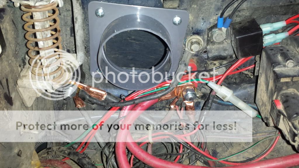
I put in new mounting lugs on the passenger side for all of the existing wiring that the battery extends to, and installed what will be the cold air port for when the throttle body moves to the passenger side. (I will eventually install a splash shield inside the fender well to keep water from going too much in there.)


On a side note, I have a lot of wiring to clean up that was messy even before I started this project. But there is a decently sized hole now. The coolant overflow is going to go into that space and hopefully leave room for the air filter.


I still have to move the battery temperature sensor. I am just going to extend the existing wiring back around for the time being until I really dig into the ECU harness.
 
When installing the AEM would be the best time to move the battery temp sender. AEM advises not to mount the AEM in the engine bay, but inside the cab. You will have to extend the wiring as the length was determined for an interior mount PCM.
 
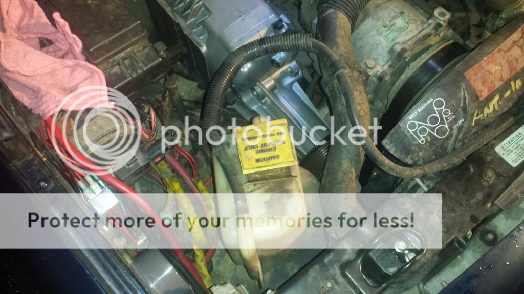
Tonight I had some more time and put in the coolant bottle in a spot that seemed like it worked. Without cutting off the battery tray mounting bolts, it fit perfectly with the lower nub into the hole from the battery drain. It also left a nice area for the cold air intake hose to go. Perfect, right?


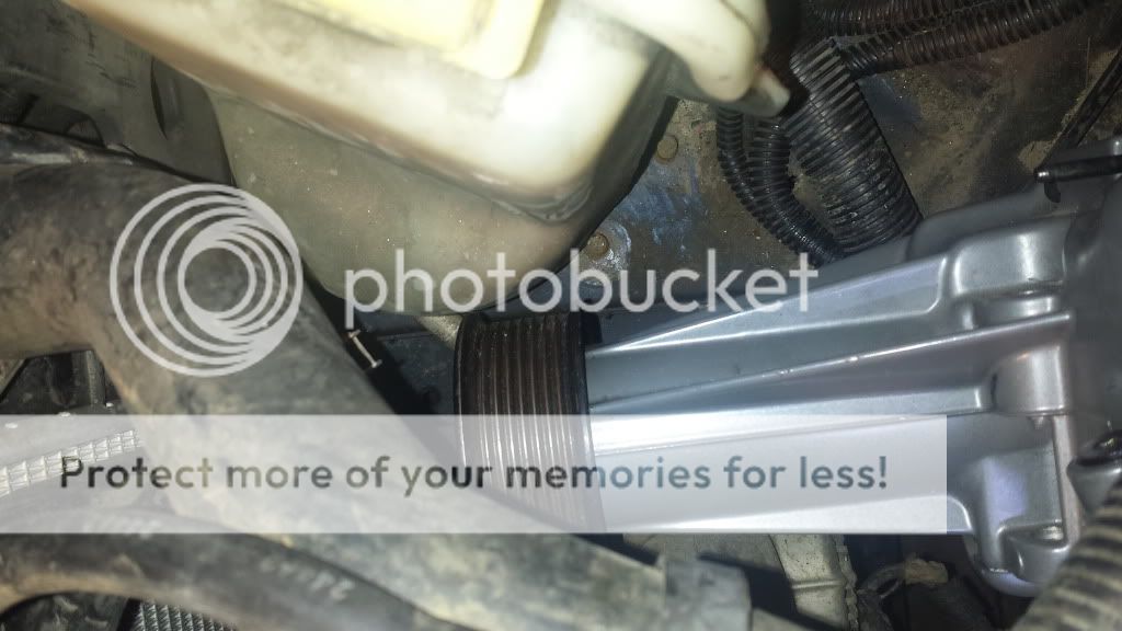
Not quite. I put the supercharger into place and this is what I saw. Keep in mind that with the current A/C condenser pipe in place, the supercharger sits almost exactly 1" rearward from where it should be.

Pulley to coolant bottle clearance (admittedly, pulley will be slightly smaller than this one)


Supercharger body to A/C compressor mount clearance


Supercharger pulley, A/C condenser pipe, serpentine belt, mechanical fan clearance.


And on top of it all, I can't even visualize a single place on the passenger side to put the air filter once the throttle body is in place. Nor have I found a place to wedge the necessary idler pulley.

The option to delete the A/C is becoming a distinct possibility. I'm open to suggestions.
 
My suggestion is dont scrap the AC.....those of us who want to copy your design like AC!
 
Check around to see if you can get a new hose made for the A/C. We have a couple of places here that can do it so I have to assume there are shops up your way.

Wiring Loom. I go to Home Depot to get the stuff to cover the wiring. Comes in a variety of diameters. Don't be concerned about the original stuff falling apart as years of heat cycling does that.

F/IC mounting. AEM does strongly suggest that the device be mounted in the cab owing to it's lack of water proof electrical connections. I have mine mounted as high in the bay as I could mount is and am very careful when washing the bay.

This photo just shows the thing. I do plan to add a simple cover for though, just have not had the energy to get it done...

HoodVent3.jpg
[/URL][/IMG]

You will have to pardon the filthy bay. It was between washing events when the photo was shot.
 
Back
Top