H.D. Offroad Engineering 3-link install
(sorry about the blurry pictures, guess I need to clean the lens)
Brian has an improved design of these brackets, so the brackets I am installing are not exactly the same but the overall process is very similar. The new brackets inboard the lower links and change the orientation of the upper rod end on the frame side. You can see what the new brackets look like here:
http://www.naxja.org/forum/showthread.php?t=1113127
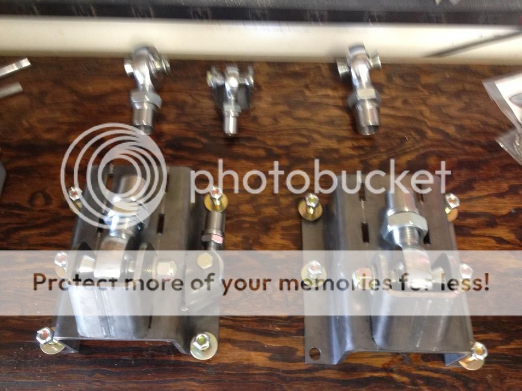
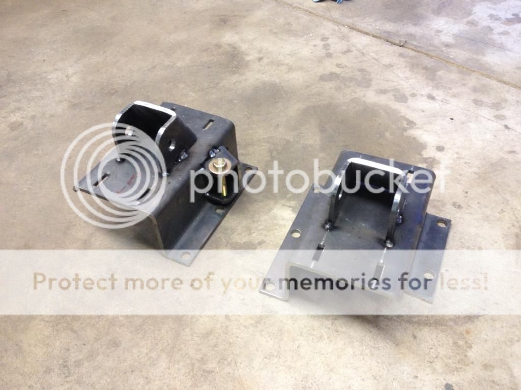
Below is the version of the brackets that I am working with. Note that some aspects of my install might be different than yours, due to my rock rails, axle truss, etc. For instance, many people prefer to run the upper link on the passenger side, whereas I will be running the upper link on the driver's side, since I could put the link mount on top of my truss. I am using 1.25" lower rod ends and a 3/4" upper rod end.
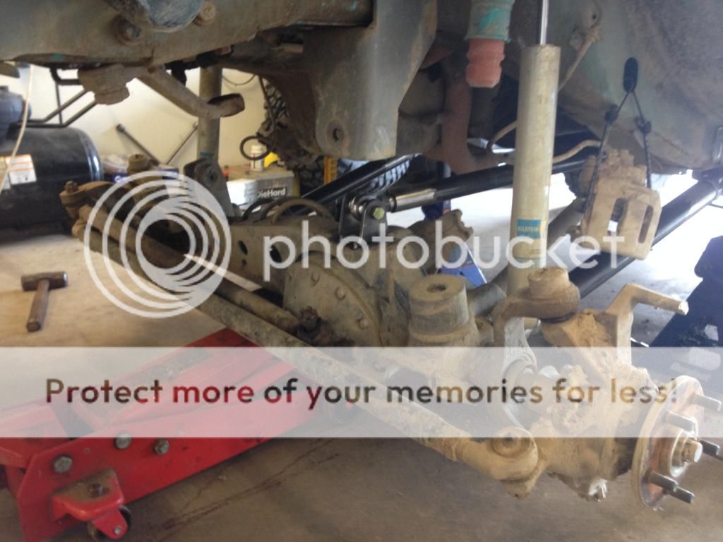
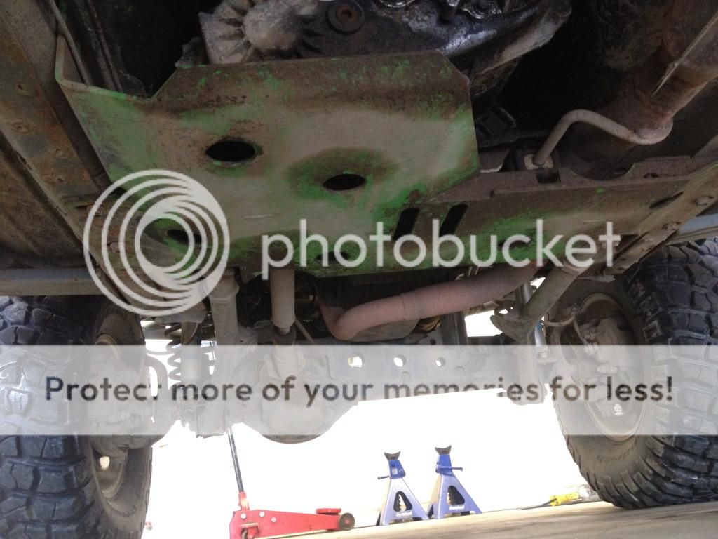
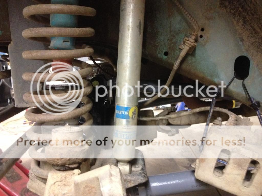
Here's what I started with, an older 1-piece TnT Y-link and belly pan.
I am only running the upper link on the driver's side, as I had some binding issues (not TnT's fault) and wasn't able to install the passenger side upper. It's not really noticeable in this picture but the hourglass bushings at the axle end are still under some bind, which produces a nice squeak every time I hit a bump. Also true to a radius arm setup, the Jeep tries to push itself back and away from any upwards obstacle. This is why I've wanted a true 3-link.
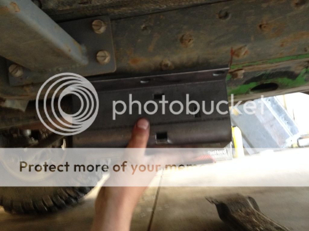
The TnT kit uses an extra bolt hole in front of the two crossmember holes, but I was planning to return to the stock crossmember. I planned to put the 3-link bracket directly in front of the stock crossmember. First problem, it hit my JCR rock rail attachment. I had ordered them to fit around TnT long arms, which either relocates the front mount, or the back mount, or both. It may not be a problem with other types of rock rails.
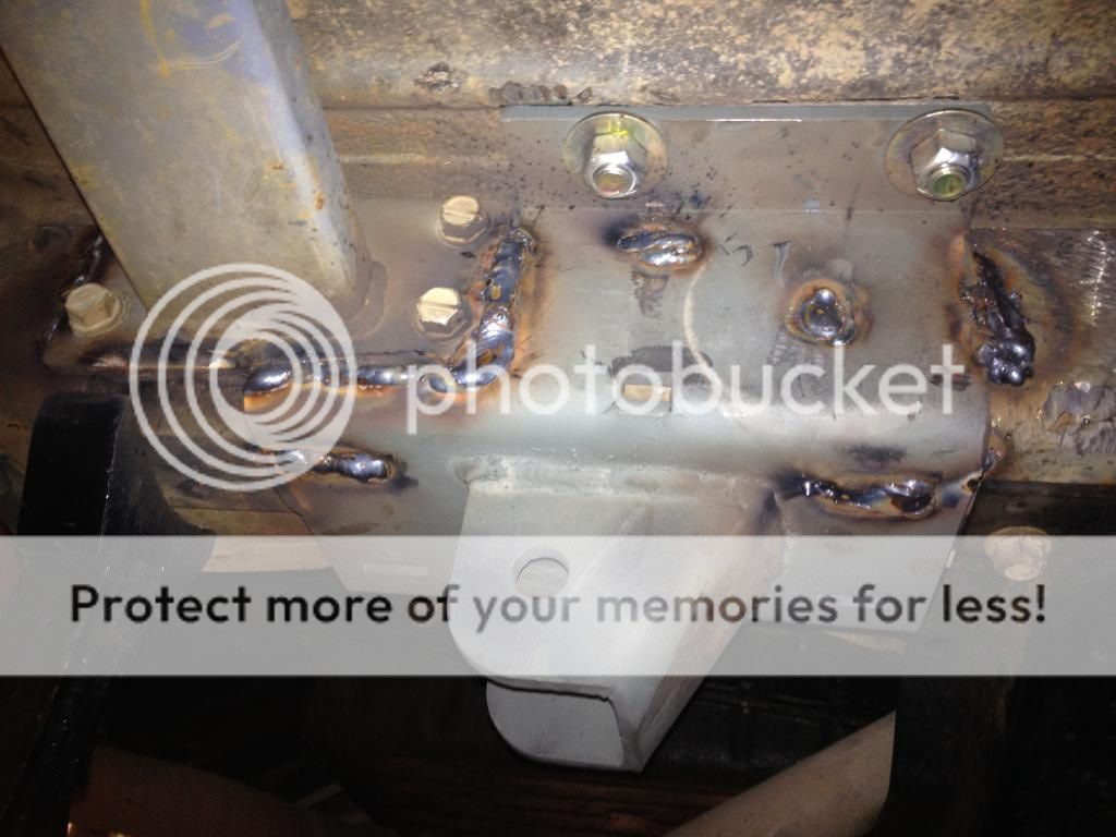
I considered a few options like moving the 3-link brackets rearward to clear the rock rail. I finally decided to weld the rock rails to my H.D. Offroad frame stiffeners, and then notch the bracket around the rock rail. I ground off the paint around where the brackets would mount so that I could weld them to the frame at the end. The brackets bolt through the floor but also need to be welded. I found it was easier to mock up just the bracket bases without the link mounts welded to them yet. Test fitting the brackets:
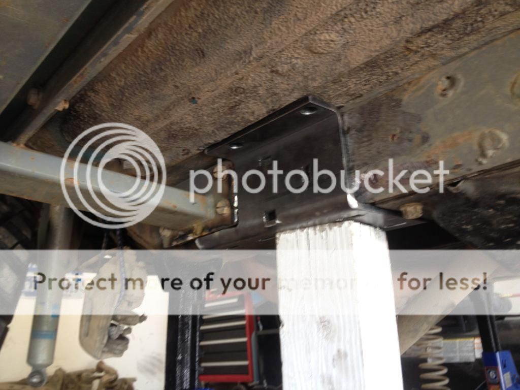
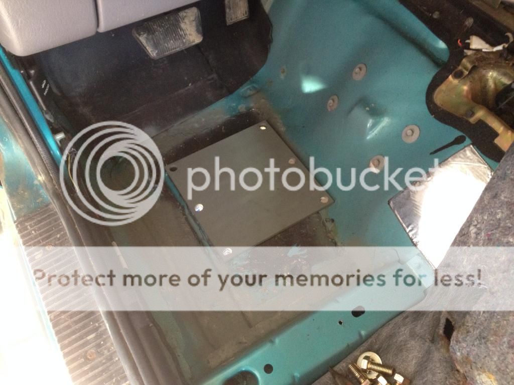
One funny thing that got me later, if you have the jackstands in front of the brackets you can't install the lower links... oops! Luckily the new design inboards the lower links and makes this a non-issue. You need to drill 1/2" holes through the floor, as there are interior plates that go on top of the floor. I pulled up the carpet inside so that I could hide the plates and bolt heads under the carpet. Even if you don't have carpet, you probably have floor mats to throw on top of them anyway.
I tacked the brackets together in case I screwed up my link placement or decision to go with a driver's side upper link. I also tack welded the nut for the upper bolt, since it's hard (impossible?) to reach after the brackets are installed.
I elected to use the middle mounting location for the lower link. I ended up with 28" lower links and a 31.5" upper link. Had I used the rearmost mounting spot, the lowers would have been around 30.5". I chose to have the upper longer than the lower to help correct pinion angle as the axle droops, though it's probably not that big of a problem.
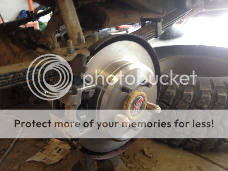
At this point I still had to deal with the upper link on the axle side, which is a common hurdle for 3-links designs as you need to have all rigid joints and eliminate the factory rubber UCA bushings. HDOE included an extra bracket to be welded to the end of the upper link, like most aftermarket upper arms (tabs on the arm and a bushing at the axle). However, if you do this you MUST replace the UCA bushing with a rigid joint. Currie (and possibly others) made a replacement UCA cartridge joint that you can use for this purpose. My truss was previously set up for universal fit poly bushings and a 1/2" through bolt. I opted instead to cut the mount off the truss completely:
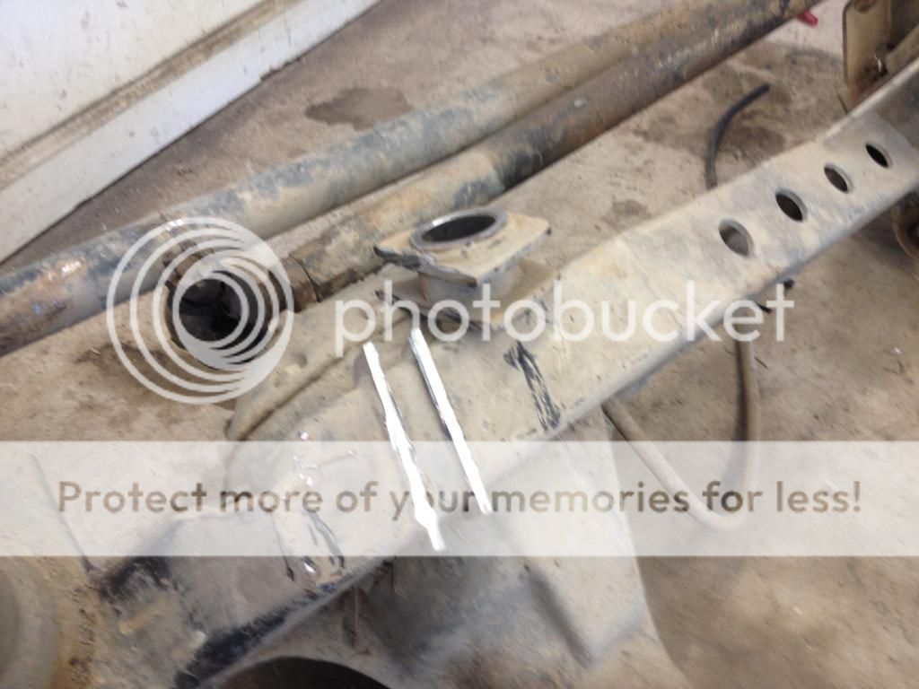
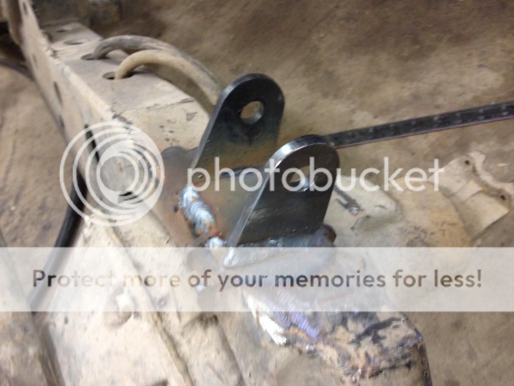
And instead I welded the supplied link bracket to the axle, and used rod ends on both ends of the link. I pushed the axle side mount to the passenger side a little bit, to help the upper link clear the brake/fuel lines. Even if I had put the link mount directly above the pinion I don't think there would be any issues with the link hitting the driveshaft.
With the brackets, links, and axle bolted in, I could cycle the axle and check for any issues.
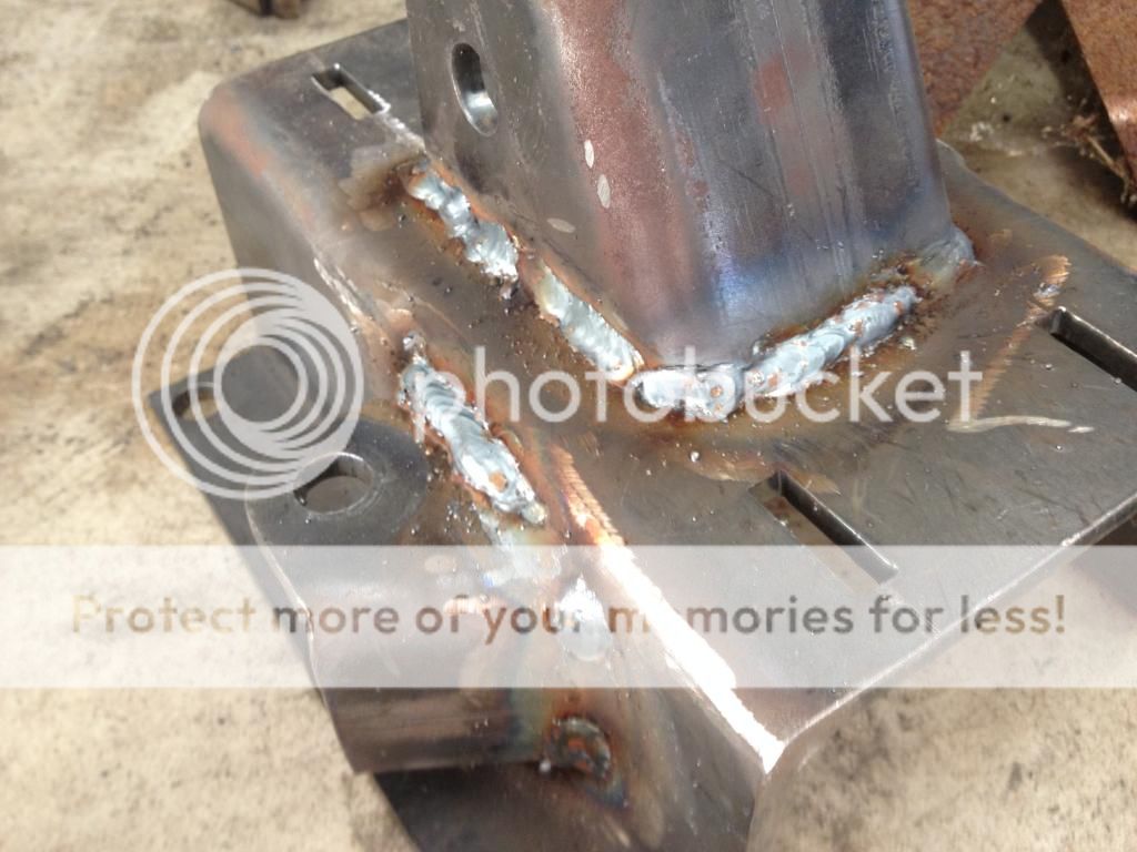
I was pretty happy with how things looked, so I took it all apart to burn it in. Oooo, ugly welds:
Yea I should probably grind some of these down and go back over them, but I figure quantity over quality. A sufficient number of crappy welds and it's not going anywhere.
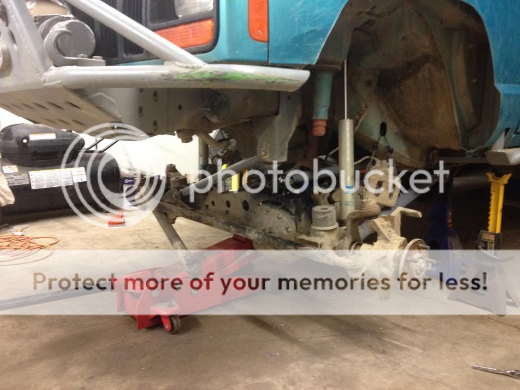
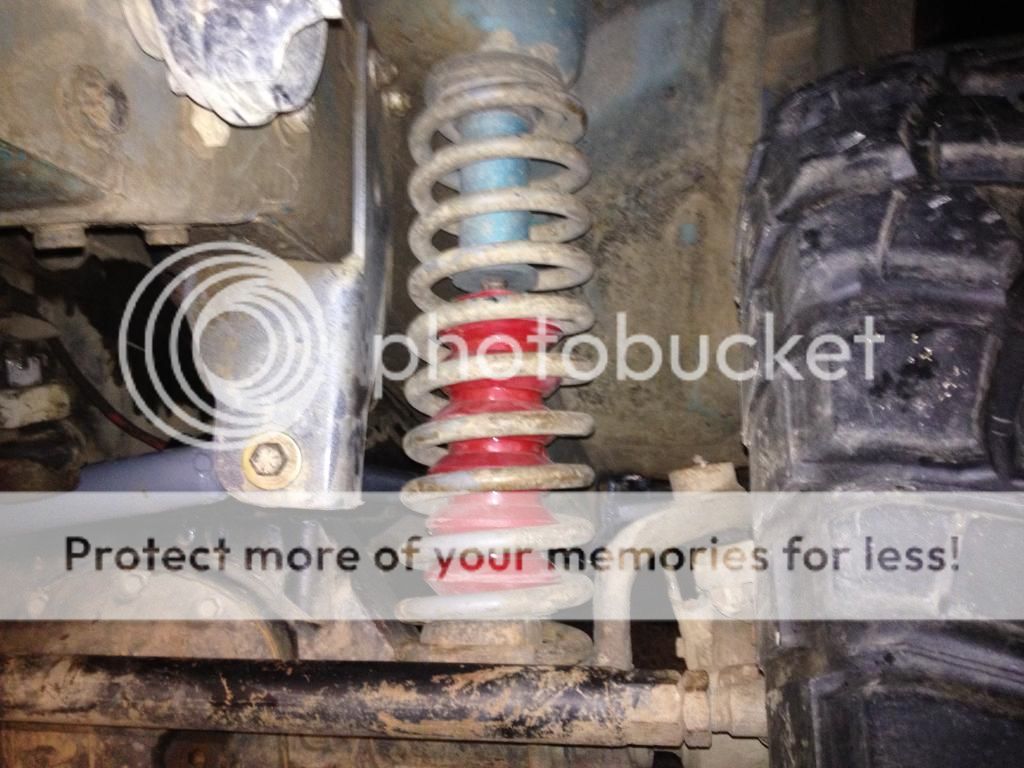
Here it is at ride height:
Here's a side view at ride height:
I tried to balance oil pan clearance, keeping the tire out of the front of the fender, keeping a couple degrees of caster and a good pinion angle. All of my links are at their minimum lengths right now, but I will probably add a 1/2" to the lowers to add some caster and bring the pinion down a little bit.
All in all this was a pretty intense project for me, but then again I work slow. I'd say it's definitely a weekend job if you have things planned out. This is something I wanted to do for a long time, I just had to wait for H.D. Offroad to make a kit!
")