Take a look at the following photo (and apologies for not crediting whoever took it originally, but I lost the thread that it came from):
This is pretty much exactly how I think I want to wire in some extra switches in my 2000. Got a few general questions about the installation, though:
- Is clearance between the pins on the back of the switch and the roof reasonably decent? My concern is bending spade connectors, etc. if they contact the headliner / roof.
- Were there any physical space issues with bringing in the extra wiring?
- Did you manage to tie in to the instrument dimmer line for the switch lights?
- What other problems did you run into, and what would you avoid doing again if you had to do it all over?
The more I look at the amount of switches I'm going to need to plumb in, that bit of plastic in the roof is looking more and more attractive as somewhere to corral them.
I've been meaning to do a write up on how I did this, just haven't gotten around to it yet. Here are some thoughts.
-Space behind the switches is fine. I had to trim out about a 2"x8" piece of headliner, but the rest of the hole is already there as it is the same location where the keyless entry module sits. Unfortunately this means that you have to move the keyless entry module a little to make room. I just cut off the mounts toward the front of the module, rotated it around 180 degrees on the rear mounts, and then glued the front mounts (now at the rear) back into the OHC in the appropriate spot.
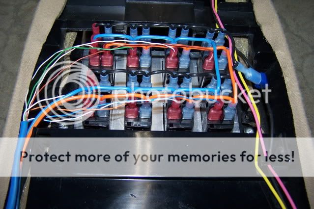
Here's a pic of the wiring (backside of the above pic) to give you an idea:
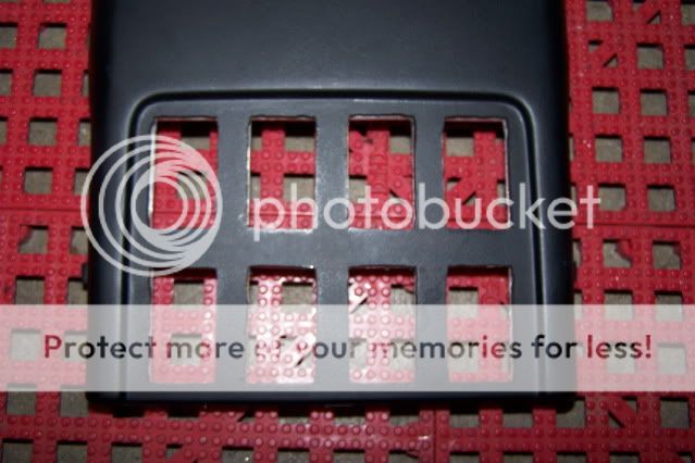
And here are some pics to show the holes in the headliner, most of which is pre-existing:
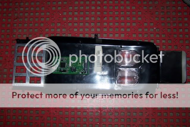
And here is the relocated keyless entry module mount:
-I ran the wire for the dimmer and the ignition switched 12V+ up the passenger side A-pillar (which was pretty tight) and ran the Cat5 cable for the switches as well as 6 power wires for my future roof top lights down the driver side A-pillar (plenty of room in there). I picked the ground up from the existing OHC wiring. I used disconnects for everything so I can still take my OHC down if I need to.
-Yep, tapped into the Orange dimmer wire just above the fuse panel by the passenger's feet and ran it up the A-pillar.
-Cutting the holes for the switches was probably the hardest part. I also cut out an aluminum backing plate which I glued to the back of the OHC to add a little rigidity. It's pretty tight and while the bezels on the switches will cover up some mistakes, you still have to be pretty careful. Someone suggested that I just cut out a large rectangle the size of 4 or 5 switches and just mount them all side by side. I personally like the look of having a bit of space between each switch.
Relocated keyless entry module and aluminum backing plate:
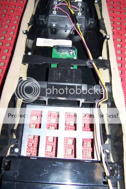
Everything in place prior to wiring it all up:
Another suggestion I recieved was using stranded Cat5 cable instead of the more common solid Cat5 cable I used for the relay trigger wires. Supposedly for added vibration resistance.
I think that answers all your questions. Let me know if you have any more. You should be able to figure it out by pulling down your OHC and comparing it to the pics I've provided. You
will need to cut out a little of the plastic that originally housed the keyless entry module, but if you do it cleanly, you shouldn't affect the integrity of the OHC at all. Let me know if you have any more questions or need any other pics. I have a bunch. I think I could also dig up the template I made on a CAD program if you're interested in doing the same 8 switch configuration.

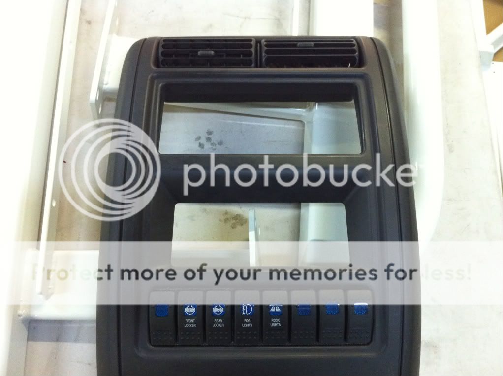

 What kicked off the planning on all this switch stuff was the decision to finally replace the existing switch faces with ones that are actually labelled as to their function; OTRATTW were the default go-to place for all that. My locker switches now light up an interesting light cyan/turquoise colour courtesy of having replaced the green indicator lenses with blue ones.