• Welcome to the new NAXJA Forum! If your password does not work, please use "Forgot your password?" link on the log-in page. Please feel free to reach out to [email protected] if we can provide any assistance.

Overhead Console Computer

Thanks for the incite. Your right, the voltage reg failed and sent a cascading effect down the board frying multiple components. Some boards appear to have less components burn that others.

I pulled this one from an 89 Caravan. The van only had 150K on the ODO so you would think it would have some life left in it. It doesn't come on when I plug it in. Can anybody see an obvious flaw with it? I was hoping this one might work.

online1.jpg

Notice the darker color of the circuit board and the display screen.
 
Just an update on the OHC project, I went to our local pull a part this weekend and took apart three consoles from 88-96 XJs that had the computer module unit. All three were burnt in the same place and appeared unusable. I then broadened my search to other Chrysler products and found two from an 89 and 90 dodge minivans. Both vans had around 150K on the odometer. Finally I grabbed a unit from a 93 Grand Cherokee. Only 1 of the van units worked. I have 2 Cherokees that needed replacement, so I tried the Grand Cherokee unit. It plugged up and came on. I would like to permanently mount the GC unit in the XJ console (since finding working 88-96 XJ computer units are rare). My first problem is that the computer unit shuts off when I turn on the headlights. The second problem is that it doesn’t fit in the 88-96 XJ console. I have tried removing some of the plastic around the dome lights. The third problem is that the compass is not working correctly (probably needs to be recalibrated) and that the temp is in Celsius. Again any help is much appreciated.


GC computer
online3.jpg


Modified 93 XJ console
online4.jpg


Showing clearance issues with computer
online5.jpg
 
The compass is self calibrating. Just drive around a bit and it will correct itself. Also to change from Fahrenheit to Celsius you need to press one of the buttons and it will convert it. I believe the temp gauge has to be plugged in for it to work though. As for making it fit I have no clue since Ive never done it before.
 
I've replaced the overhead 3 times and each had the exact same symptom: Compass & Temp display dashes but Elapsed time works ?!?!?!?!?!?
 
the compass will not calibrate itself. you need to drive in 3-5 counter clockwise circles to calibrate it. then the little 'cal' will go away.
 
Old post - newbie just joined

I had the same problem (compass/temp board didn't work) and fixed the problem on two different boards. The components in this section are simply isolating capacitors. The regulator on both boards checked out perfectly. The real problem is that this section of the board gets pretty hot and one of the key traces is sized too small. Over time (and heat cycles) this trace seems to tear off creating an open circuit. I simply added a piece of wire to both boards to replace this trace and both boards started working again. I don't know how to post pictures so if anyone wants a pic of where to solder the wire send me a PM with your email address.

Your mileage may vary but it worked for me.

HTH
Todd
very nice! I should have caught that :dunce:

Picture posting - if you have the pics on your computer, do this:
go to www.imageshack.us
click the "Browse" button next to the text box under the line saying UPLOAD:
select your picture(s) (you can hold down control to select more than one, just hold control and click each one, or click the first one and then hold shift and click the last one if you just want to select a large number of photos all in a row), click Open
click Upload Now button (blue)
when the upload finishes it will send you to a new page. click the text in the box beside the heading "forum thumbnail" and press C while holding control key (or right click and select copy from the menu.)
paste the code into the forum post text box, optionally remove the "uploaded with imageshack.us" line.
 
Ok, lets try this. The connection that breaks is highlighted with the red line. You can try to squeeze a small piece of wire and a soldering iron into this space or simply turn the board upside down and solder a piece of thin wire (I used a piece of telephone cable - nice and small) between the negative post of the electrolytic cap (highlighted in the blue box) and the #3 pin (center pin) of the regulator. In reality, any ground point will do but the regulator is pretty convenient.

HTH
Todd


very nice! I should have caught that :dunce:

Picture posting - if you have the pics on your computer, do this:
go to www.imageshack.us
click the "Browse" button next to the text box under the line saying UPLOAD:
select your picture(s) (you can hold down control to select more than one, just hold control and click each one, or click the first one and then hold shift and click the last one if you just want to select a large number of photos all in a row), click Open
click Upload Now button (blue)
when the upload finishes it will send you to a new page. click the text in the box beside the heading "forum thumbnail" and press C while holding control key (or right click and select copy from the menu.)
paste the code into the forum post text box, optionally remove the "uploaded with imageshack.us" line.
 
Last edited:
Ok, lets try this. The connection that breaks is highlighted with the red line. You can try to squeeze a small piece of wire and a soldering iron into this space or simply turn the board upside down and solder a piece of thin wire (I used a piece of telephone cable - nice and small) between the negative post of the electrolytic cap (highlighted in the blue box) and the #3 pin (center pin) of the regulator. In reality, any ground point will do but the regulator is pretty convenient.

HTH
Todd

Not quite - you copied the wrong URL I think. Had enough info in it that I could fix it though!

Thanks a ton for posting this, I'll definitely have to remember this and refer people to this thread when the question comes up.

EDIT: ok, you got it now! :thumbup:
 
The FSM says to make 4 complete 360 turns, as tight as possible, to calibrate the OHC compass. I can attest this works..

The best part of the OHC issue is that all Chyrco Products from similar year models will have the same electronics. I installed an OHC in my Wife's (now sadly departd) 1989 Grand Wagoneer using the OHC from a 90. Had to replace the display as the "Jeep" unit was shot. Pulled one out of a 91 Grand Caravan along with the ambient temp sensor. Installed the parts and viola! All worky again.
 
I have had quite a bit of success fixing these boards and I have had some people reach out recently (after finding this post) asking for details on how to fix theirs so I thought a write-up might be in order. I will also place a parts list near the bottom.

The Problem

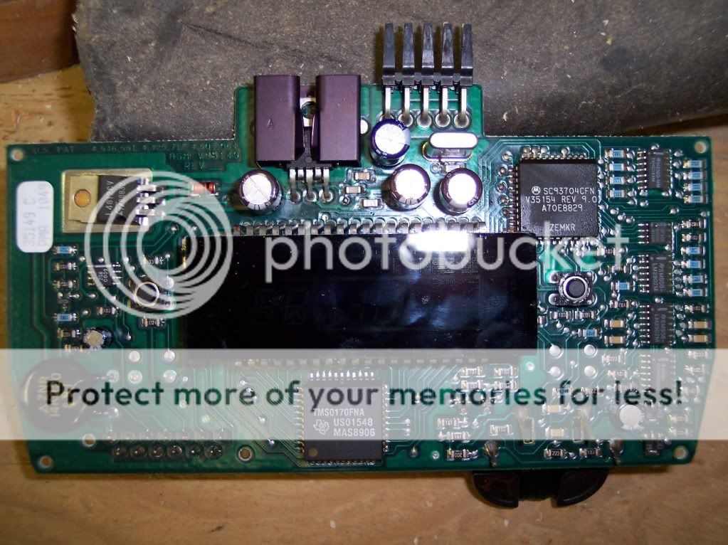
First, the area that typically gets fried sits around a 5volt regulator which is highlighted with a white arrow in the picture below. From what I am seeing, the cause of failure always seems to be one (or all) of the electrolytic capacitors highlighted in the blue boxes. This makes sense because electrolytic capacitors tend to last a LONG time but what can kill them is heat and sitting next to the roof of an XJ for 20 years is a pretty sure way to accelerate their demise. The problem is that when they blow, they take other components (and traces) with them. The 3 small ceramic capacitor to the right of the voltage regulator (numbered 1-3 in orange)are prime targets for this. These 3 capacitors can actually be removed since they aren't really needed in this circuit but I will include a section below on how to change them out if you prefer.

Power Circuit
The real issue is that when the electrolytic capacitor blows, these little caps get really hot and often cause some of the traces to break. The one highlighted in red is often bad and this one is very important since it is what provides the ground signal to two of the electrolytic capacitors. To test this, turn the board over and connect a mult-imeter (set to ohms) between pin 3 of the regulator and the negative pole of each capacitor (marked with the white bar and a "-" sign on the sides of the capacitors). When you connect your meter to these points, each should read close to 0 ohms.

CPU Reset Circuit
The other trace that tends to get burned up is the one that connects pin 2 of the regulator to the CPU. This pin provides a 4.6-4.7v reset signal to the CPU and if it is broken, the CPU won't turn on. The best way to check this trace is to use your multi-meter again (still on the ohms setting) between pin 2 of the regulator and pin 5 of the CPU (both ends highlighted with the yellow arrow). When you connect to these you should also get a reading of close to 0 ohms.

The Fix

If both of your multi-meter tests are good, you should be able to simply replace these three capacitors. All 3 are 100uF 35V capacitors and are available online or from places like Fry's Electronics. Typical cost is ~$1.50 each (3 needed).

Power Circuit fix
If you found a broken trace between pin 3 and the negative poles of the electrolytic capacitors, the easiest fix is to turn the board over and solder a wire between pin 3 (ground) of the regulator and the negative pole on one of the new electrolytic capacitors. This essentially re-attaches the connection I highlighted with the red line in the pic. Here is an easy trick: rather than looking for small wire, simply use some of the excess wire you will cut off the bottom of the capacitors and slide some heat shrink tubing over it. This will insulate the wire to keep it from touching any other part of the circuit.

CPU Reset Circuit fix
If you found a broken trace when you checked the connection between pin 2 of the regulator and pin 5 of the CPU, the fix is a little harder. The break is usually on a small trace that runs right between the orange 2 and 3 in the pic. If you look closely at the pic, there is a small solder spot directly under the orange number 3. What this hole does is connect the trace on the top of the board to another trace on the bottom of the board. If you connect your multi-meter between this solder blob and pin 5 of the CPU, it should read 0 ohms and if so, I typically turn the board over, heat up this blob and feed a small wire through it. I then attach the other end of the wire to pin 2 of the regulator (using heat shrink insulator again).

Burned up ceramic capacitor fix
This fix isn't really necessary since the board will work perfectly without these capacitors but if anyone wants to change them out, they are all 100nF and can be replaced on the backside of the board with traditional ceramic capacitors. These cap's are simply used to try to protect the voltage regulator when something goes wrong. I have numbered them in the pic and the connect as follows:

#1 - connects between pin 3 of the regulator and the positive side (opposite of the side marked with the white bar and "-" sign) of the middle electrolytic capacitor.
#2 - connects between pin 2 and pin 3 of the regulator
#3 - connects between pin 3 of the regulator and the positive side (opposite of the side marked with the white bar and "-" sign) of the right-most electrolytic capacitor.

Test
Once you have done all this, you can reinstall in the Jeep and check that it is working. Alternatively, if you have a 12volt power supply available, you can connect power to pin "1" and ground to pin "e" to test the circuit on the bench. Note that you may have to press the "Comp/Temp" button to turn it on.

a b c d e f - this side is towards the center of the board
X X X X X X
X X X X X X X
1 2 3 4 5 6 7 - this side is towards the center of the board


Parts list
(3) 100uF 35v Electrolytic capacitors - ~$1.50 each at Fry's Electronics or Radio Shack
http://www.radioshack.com/product/index.jsp?productId=2102510
(1) L487 5volt regulator - ~$5.00 on eBay (probably not needed since this regulator can take a LOT of abuse.)
(3) 100nF ceramic capacitors - $0.62 each not really needed
http://www.radioshack.com/product/index.jsp?productId=12401429

Tools Required
a half decent soldering iron is required - ~$10.00
http://www.radioshack.com/family/index.jsp?categoryId=2032313&sr=1&origkw=soldering%20iron

some solder
http://www.radioshack.com/product/index.jsp?productId=2062719

a vacuum desoldering tool comes in handy - ~$10.00
http://www.radioshack.com/product/index.jsp?productId=2062745
 
Last edited:
Very good work - one minor note. The 100nF caps are actually what is called decoupling capacitors, they absorb high frequency switching transients on the supply lines from the various chips changing output state from 0 to 1 and vise versa. They aren't really there for emergencies, more to keep everything stable. A good design engineer will put one on the input and output of the voltage regulator, one next to each chip's power pin pair, and spread a few more around the board for good measure since they are super cheap, under 1 cent each in production volumes. In fact I found some (X5R temp coefficient, 0402 package) for 0.17 cent... if you buy 50 thousand!

Anyways, they are basically there to suppress noise in the power supply circuits and a good engineer will have put plenty in, because noise is difficult to predict and even harder to debug and all customers care about is the device not crashing. They aren't impressed by your "well this is super interesting, never seen that data corruption before, this tenth of a cent capacitor I skipped to save money must be at fault" explanation. So you could probably lose five or ten of the decoupling caps on any given digital logic board and still have it work... as long as you have good luck. I don't count on my luck, so I put decoupling caps everywhere they are traditionally put.
 
Kastein,

You are correct but I noticed that all of these ceramic capacitors (except the reset circuit which doesn't really matter since the CPU is simply looking for a steady ~4.7v signal) are in parallel with the electrolytic caps. As such, the electrolytic caps should perform the same function (eliminate noise).

For those of you "adventurous souls", the datasheet for the voltage regulator is shown here (note that this board doesn't use pin 4 at all) and the designer was kind enough to place the Patent numbers on the board so if you want to know how this thing works, you can review the schematic and theory of operation at the bottom link:

http://www.datasheetarchive.com/dlmain/Datasheets-112/DSAP0044966.pdf

http://www.google.com/patents/US4546551
 
You're nearly right (and it's great to see someone else on here with a pretty solid grasp of electronics, we need more EE types here) - but not taking into account the effect of capacitor effective series resistance (ESR) and lead inductance on their efficacy in a filter/decoupling application. Filter caps are typically large capacitance aluminum electrolytics, as seen here, but their crummy ESR and lead inductance specs mean they don't filter the totem pole output commutation current spikes created by digital ICs very well. Thus, we normally drop a 0.01 to 0.22uF ceramic or other low-ESR cap as close to each IC as possible to soak those transients up.

An example - a while ago I was designing a small embedded automotive CAN bus module to interface with the brake hydraulic pressure sensors and fuel level sensors on a prototype vehicle at work. I started out with an LM78L05 voltage regulator with a 1uF tantalum and a 100nF MLC (multilayer ceramic) capacitor each on the input and output, a fairly standard 78xx series linear regulator filter topology. You'll see it in millions of devices worldwide in fact. A few weeks into the design process, a few more sensors were added to the module's interface and suddenly I needed more than the 150mA the 78L05 can supply, so I dropped a Micrel MIC5239-5.0YM in instead without much thought. When I powered the board up for the first time the voltage was all over the place - jumping from 7V to 10V, and incredibly noisy! After reading the datasheet I realized that Micrel specs a much larger 10uF bulk filter capacitor, which solved the voltage output instability issues, everything was stable at 5.025V... but there was still a ton of noise. After poking around a bit with my oscilloscope I determined that the noise was strongest near the Atmel AVR AT90CAN128 MCU. I had not finished populating the board yet (as I was just checking supply stability before continuing, I assemble my first rev of any prototype one stage at a time to simplify debugging) and was missing a pair of decoupling capacitors on one of the three pairs of VDD/VSS pins on this MCU. Soldering that pair of silly little MLC capacitors in place reduced the magnitude of the supply noise by 14dB.

As for the reset circuit - the way most of those work is a capacitor to ground and a resistor to VCC/VDD. The reset pin is generally active low, the capacitor starts out discharged (and therefore at 0V) holding the MCU in reset state until the voltage rises as the capacitor charges through the resistor enough to bring it to the 4.7V level you cited. This may or may not be how this particular reset circuit works, so I could be wrong, I'd have to look at the board again to be sure. I've also seen dedicated reset control devices such as the dallas semiconductors DS1233 used before.
 
Oh, also - thanks a ton for the patent link, I will have to read that tonight. I knew the compass sensor was a ferrite core with two windings around it at 90 degrees to each other, but not how exactly it worked. Very interesting!

Edit: the reset circuit is as I said, but with one really cool added feature - they put a reverse biased diode across the resistor. What this does is discharge the reset timing capacitor much faster when the vehicle is turned off so that a momentary loss of power that might confuse the CPU but would not trigger a reset without the diode also triggers a reset.
 
Last edited:
So, I have 3 of these things that were sitting in storage for almost 10 years. None of them work. After reading the posts here, I ordered new electrolytic and ceramic capacitors. After disassembling one of the boards, I tested all the caps with my LSR meter and they checked out okay. Even the burnt ceramic caps passed. Since I had new ones, I replaced them anyway. The traces between all the caps were still intact, even though one was slightly lifted.

I have 4.7V reset signal at the microprocessor.

I have 5V logic supply voltage at the microprocessor and the display driver for the VFD

The display driver fires up and supplies 2.8 volts to the VFD cathode filament wires. They faintly glow red in complete darkness.

I have 11V from the display driver to the VFD grid.

I tested all the Q outputs from the display driver to the anode pins on the VFD and I barely get 30mV on each one. I can manually operate the display by bridging the 11V from the grid pins to the anode pins and the individual segments will illuminate. That shows there's nothing wrong with the display itself.

I'm having a hard time troubleshooting this because I can't find a datasheet for the Motorola microprocessor or the TI peripheral display driver. It seems to me like the display driver might be at fault, but i'm not 100% sure. Is there any way to verify if the display driver is receiving data over the serial bus from the microprocessor?

All 3 of these PCBs have the same problem. If we can find a solution to this, I'm sure it will help a lot of people.

Here's a picture of how all my VFDs currently look on all 3 boards.

https://scontent-a-lga.xx.fbcdn.net...20_1520559551526992_7836525216960367311_o.jpg
 
Try momentarily bridging the reset signal at the microprocessor to ground with a jumper wire. Right at the microprocessor pin, not on the positive side of the resistor - that would short the logic supply to ground. I doubt this will solve the issue, but if it does, you've got a reset circuit startup issue - and it's a 30 second test to perform, so it's worth trying even with little chance of success.

Sounds like you are on the right track otherwise. 2.8 volts for a VFD filament sounds kinda high to me (I am used to only a volt or so) and it appears to be glowing pretty brightly, but that may just be your camera being far more sensitive to infrared than our eyes are. Either way, it should be lighting up, so you definitely have some sort of logic/segment driver issue.
 
Tried grounding the reset pin and it didn't seem to have any effect. My benchtop power supply shows the board is drawing 260 milliamps, so it is partially powered up at least. The voltage regulator gets pretty warm, but not excessively hot.

I'm not sure if this means anything, but I get 72mV at the anode pin for the segment at the C/F part of the temp display. I would think that the voltage should show fluctuation when i press the Celsius/Fahrenheit button since it would be turning on and off. It stays constant though.

BTW, the filaments look really bright because it was a 30 second exposure. They aren't even visible normally except in total darkness.
 
Back
Top