• Welcome to the new NAXJA Forum! If your password does not work, please use "Forgot your password?" link on the log-in page. Please feel free to reach out to [email protected] if we can provide any assistance.

No Aux fan with A/C or by temp....can I swap ABS relay to test?

So what's my problem?
so no power to that socket but where does that wire come from? Do I need to replace it?
I only see one mini 20A fuse, but my fuse tester's broken. I'll see if I can dig up a 20a mini.....

Edit: Gonna run to the store n get some minis.
 
Last edited:
Checked all fuses and # 15 (30A) was blown.
I've read #4 #13 and #11 and the mini 20A fuses are the ones to check.
I then cross referenced my 95 AND 96 FSM (stupid crossover year, electrical is mostly 95 like the fuse box NOT in pas side panel etc. ,other stuff is 96+)
Paraphrased from the FSM:

"Fuse 13 supplies battery voltage to the contact side of the radiator fan relay on circuit F141 (I had to learn to read schematics here lol)

Circuit A14 from fuse 15 in the PDC powrs PDC fuse 4."


I now have 12V to socket terminal 30. Also picked up a NEW relay.
Now to start and try it out.
Here goes nothing! :eek:
 
I think you found it. Good job! :thumbup:
 
Nope.

so how do I test the temp sender? If I unplug it while running the fan does not come on.
Does that mean the sender is bad?
Is it possible the fan won't kick on with A/C or heat because of low refrigerant?
My head hurts:banghead:
So to sum up: The relay clicks, the fan works when jumped, the wires are good from fan to PDC, the sockets all have good continuity or voltage where required, after ohming the temp sensor it checks out, all fuses are good and a NEW relay.
AC compressor kicks on but no fan even after 20 minutes.
fan does NOT kick on at 220+ if my gauge is accurate an it always has been.

Help?
 
Last edited:
So the #15 30A fuse I just replace blew again the moment the fan relay clicked.

Edit. According to the 95 FSM I need a 20A fuse in #15 in teh PC NOT a 30 A fuse. Is that why the fuse blew?
I'm trying to figure this out.
Anyone? What am I dealing with here???????????
 
Last edited:
The PDC cover says it's a 30A fuse, so.....

I've tested the socket the fuse plugs in to and there is infinity on one terminal.
How do I fix and why did it blow?
 
Check for power (or ground? can't remember which one is supplied to trigger the relay) at the relay socket when the AC kicks on. Is it getting signal? If the relay works, the fan works & the wires are good - that's all that I can think of: signal to relay.
 
87 is an output pin, is it not?
Do you mean 86 or 85?
The fuse blew because a power wire (or the fan motor, internally) has contacted ground in a way that the factory didn't intend. If the new circuit passes too much current, the fuse blows. So you are looking for a problem in the wiring - unless you blew the fuse while you were tinkering.
 
Sorry I meant 30 not 87. Getting frazzled.
Had power to 30 on or off as I should, till the fuse popped.

Gonna grab a few fuses in the morning and try to narrow down what's popping it.

Am I correct in assuming the issue is PAST the fuse?
 
So according to the wiring diagram, there is only 1 wire supplying power from the battery through fuse 15. Testing between the output on fuse 15 and the input on the fan relay, I get an open circuit.
This leads me to believe that the problem is in teh wire connecting #15 to teh relay i.e. a short.

Is that correct??


I've tested for continuity between the signal wire (87) and a goo ground and get 0, so the wire's good RIGHT? Still "getting" all this slectrical stuff so confirmation of my assumptions would be awesome.

Edit: If I haven't said it before I LOVE NAXJA! I'd have been so screwed countless times without this forum! Shout out to Yossarian, Hypoid an Pelican in particular!
thanks so much guys for helping my inept butt understand all this lol!:cheers::cheers:
 
To clarify I believe I have a short between the output on fuse 15 an dthe input #85 on the fan relay.
I have to take apart the PDC don't I? :(
 
No.
Remove fuse & relay.
Being sure which pins you want to test, set your DMM to "ohms" and check for continuity between the two. You should see less than 0.5 ohms. If you can't get the DMM probes in there properly, make some little adapter tools out of bits of wire & the appropriate spade connectors
 
To clarify I believe I have a short between the output on fuse 15 an dthe input #85 on the fan relay.
I have to take apart the PDC don't I? :(
NO! Pin 85 is the control side of the relay.

I'll 'splain this the way I understand it: In all reality, the relay is nothing more than a switch that uses low amperage current to control high amperage current. The two never meet in the middle.

You stated that the fuse blew when the relay clicked. The fuse protects the high amp wiring that runs through the relay. Pin 85 has nothing to do with that.

When you check the continuity in the wires, as yossarian19 described, you want to see infinite Ohms between pin 30 and ground. Anything else says you have a short to ground between pin 30 and the fuse holder.

Next, unplug the fan, check continuity between pin 87 and ground. Again, the meter needs to show infinite Ohms. Anything else says you have a short in the wiring, on that side of the circuit.
 
30 to ground I get infinity.

with fan unplugged, 87 to ground reads infinite as well.


Where is this leading me.

Making a trip up to Mt Hood. A little nervous.
I'll check in in an hour if nothing explodes lol.
 
Last edited:
I may be confuse as to which terminal is which on teh relay / relay socket.

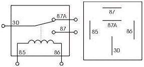
The relay I'm using looks like this:
http://www.amazon.com/Bosch-332019150-Relay/dp/B0010ADJIE
Except on the diagram on one of my relays the 1 and 2 are reversed. Likely immaterial unless NAPA sold me a reversed relay (??) mistakenly from their computer inventory.

In my FSM it's very confusing as to which pin is which and what does what as the connection #'s in the diagram are only for the FSM reference not the actual relay pin numbers on the relay itself (12345.....85 86 87 30).

Can ya'll tell me what pin goes to each of these functions so I can avoid more confusion??? I.e. 87, 30 etc. I feel like I should have diagnosed it by now but mixed something up and missed it.

???? = Fused Ignition Switch Output

???? = Fused Battery +

???? = Radiator Fan Relay output

???? = radiator fan Relay Control (signal?)
 
Last edited:
With fuse out an relay out, on pin 85/signal I get infinity. With AC on clutch activated, I get less than infinite, but not 0. That mean anything??
 
Look at the picture on the right and tell me if that is what your relay looks like on the bottom:

5-pin-12V-automotive-relay.jpg
 
Back
Top