• Welcome to the new NAXJA Forum! If your password does not work, please use "Forgot your password?" link on the log-in page. Please feel free to reach out to [email protected] if we can provide any assistance.

Ground strap on head to firewall

Since the fan relay is exactly the same, I used that instead-
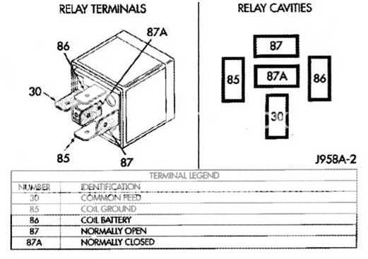
Pin 85
Key off- 0.001-0.004V
Key on- 0.10-0.13V

Pin 86
Key off- battery voltage
Key on- battery voltage

And I just noticed, even at key off pin 86 has battery voltage on both relays? Is that not supposed to be?

I had the battery charger attached so Im not sure if that varied anything. But now both pins always have battery voltage? I think I am going to try swapping PCMs to see what kind of results I get.
I have been hearing alot of negitive about my alternator charging voltage which is 16.5V 330A on a 14V system.
Lets see what I can get my hands on
 
Last edited:
For some reason I cannot edit previous posts..
But anyways I think I confused the pins before, and here are the results side by side.


Fan Relay ///ASD Relay
#86
key off- 0.000-0.002V ///0.000-0.003V
key on- 0.076-0.084V ///0.002-0.010V

#85
key off- 0.002V ///0.002V
key on- battery voltage ///battery voltage


I am thinking at key on for the ASD relay in pin #86 the voltage should be higher? Would this indicate a bad PCM?

You've got the pin cavities wrong.

Pin 86 should have zero volts with the key off, and battery voltage with the key on.

Pin 85 should have approximately .02-.03 volts with the key on or off.

Review this pin cavity guide:

Copyofimg301.jpg


The reason I suggested check the fuel pump relay pin cavities is because we know the fuel pump circuit works okay. The status of the electric fan relay circuit is unknown and may get you off on a wild goose chase if the readings differ from the ASD relay.

What voltage setting are you using on your meter? 20VDC?

I see have like double readings, i.e.:
key off- 0.000-0.002V ///0.000-0.003V
key on- 0.076-0.084V ///0.002-0.010V

Are these voltage readings cycling back and forth?

Try the fuel pump relay. Make sure you have the correct pin cavities.

The reason for this exercise is to see if the ASD relay circuit between the relay socket and the PCM are intact.

My voltmeter just has AC and DC on it not sure? Its a fluke.
Well in that highlighted section above, I was comparing the fan to ASD.
Yes they are cycling pretty rapidly up and down.

It is indeed PIN 85 that is getting battery voltage at key on.
I double check triple checked.
I am using the relay itself to determing where pin #85 is.
 
Excuse me if I am wrong.
But If I am getting voltage at the rail around 7V, and 49psi fuel pressure while cranking,

Then isnt the ASD relay working fine? I thought it was there to control ignition and fuel functions?
 
bump for info? Doesnt anybody know this?
I sure as hell dont lol

This is my only car need to get it running!
I guess you should check the FSM.
 
'FSM' = "Factory Service Manual". There are usually two of 'em these days, i.e., one for mechanical issues, and one for electrical issues. You might try e-mailing: [email protected], (which has a web site yet under construction offering exact reproductions of FSM's), or try 'googling', or check out eBay.com for new, or used FSM's for your specific model. BTW: do not just go to the eBay automotive section, as some seller just might place what you are looking for in some other indexed location. In other words, search the entire site. I have found that gaining, (for the, or any vehicle in question), all varieties of applicable after-market service type manuals, Chilton's, Hayne's, etc., are all of additional value as they seem to have more, or less information on the issue you are interested in. Original Equipment Manufacture, (OEM), FSM's, i.e., OEM FSM, may, or may not have errors, may, or may not have adequate drawings, photos, etc., as well, and hence additional hard copy books can be handy in order to really hammer on the issue at hand.

Another thing.., please indicate how you resolved your issue. Annoying to follow a topic string on a problem only to find that the questioner does not offer up a successful conclusion, or not, lol. Best wishes.:lecture:
 
Excuse me if I am wrong.
But If I am getting voltage at the rail around 7V, and 49psi fuel pressure while cranking,

Then isnt the ASD relay working fine? I thought it was there to control ignition and fuel functions?

If you are getting voltage at the rail connector while cranking the engine it may mean the crank sensor and ASD relay are wotking; however, 7 volts is too low, it should be 12 volts. Make sure you are working with a fully charged battery when doing these tests.

Here's a pinout of the rail connector. Read from pin cavity
2 to a spot on the engine as ground while cranking the engine. with the fully charged battery you should see battery voltage (12 volts).

Pin cavity 2 gets its power from pin cavity 87 of the ASD relay then through fuse 18 in the PDC.

The rest of the previous tests looks like it took a wrong turn somewhere so just button all that up for the time being.


2000XJIgnitionRailpinout.jpg
 
'FSM' = "Factory Service Manual".
Another thing.., please indicate how you resolved your issue. Annoying to follow a topic string on a problem only to find that the questioner does not offer up a successful conclusion, or not, lol. Best wishes.:lecture:
That would be a good idea.
Thanks for going into detail about which one I would need. And of course! I always report back.

If you are getting voltage at the rail connector while cranking the engine it may mean the crank sensor and ASD relay are wotking; however, 7 volts is too low, it should be 12 volts. Make sure you are working with a fully charged battery when doing these tests.

Here's a pinout of the rail connector. Read from pin cavity
2 to a spot on the engine as ground while cranking the engine. with the fully charged battery you should see battery voltage (12 volts).

Pin cavity 2 gets its power from pin cavity 87 of the ASD relay then through fuse 18 in the PDC.

The rest of the previous tests looks like it took a wrong turn somewhere so just button all that up for the time being.

Where do you keep getting all these great pin out diagrams ha
Well I would say thats part of the problem, my 14V battery doesnt play well with 12V chargers. And I dont know anywhere I can purchase a 14V charger.
So I will have to guess the 7V at the coil rail is because of my low battery.

But in regards to previous tests,
getting battery voltage at #85 pin would indicate?
I am positive that is where I am getting voltage
 
So wow, A bunch of codes here I just scanned. After reconnecting the PCM.
Let me add to that, I have had a dead battery for a while,
(14V battery no 14V charger). When I attempt to crank, I am using a jump box.

P0340 Camshaft Position Sensor 'A' Circuit Malfunction
P1493 RCNT Solenoid Circuit Malfunction
P0122 TPS Low Voltage
 
Getting 5V to the connector at the two outter most pins of the camPS connector
Are the two connector pins supposed to be seeing 5V or just one?


Also in the ASD relay #85 and #30 are seeing battery voltage at key on.
Are both pins supposed to be seeing battery voltage at key on?
Really starting to think its a PCM the more I find out

I Am still waiting for somebody to come by to check on the voltage to the coil rail
 
Last edited:
Correct me if I'm wrong,
But the 3 connector pins on the CamPS should be:

Sensor signal
Sensor ground
Sensor power - this being the only one that should be seeing 5V?

Why would I be seeing 5V at key on with two of the pins in the CamPS connector?
 
Back
Top