-
Welcome to the new NAXJA Forum! If your password does not work, please use "Forgot your password?" link on the log-in page. Please feel free to reach out to [email protected] if we can provide any assistance.
You are using an out of date browser. It may not display this or other websites correctly.
You should upgrade or use an alternative browser.
You should upgrade or use an alternative browser.
Another fuel gauge issue...
- Thread starter VAcherokee
- Start date
VAcherokee
NAXJA Forum User
- Location
- Madison Heights
What is the voltage value from Pin 3?
On the OE or Airtex? what should it be? If you know what the voltages should be, please post them and I'll check again in the morning. It's pitch black outside.
Thanks!
On the OE or Airtex? what should it be? If you know what the voltages should be, please post them and I'll check again in the morning. It's pitch black outside.
Thanks!
I was thinking if the voltage from Pin 3 is not at ~5 volts it would effect the fuel ga. sending unit circuit output.
I don't have any specifications for the PCM or the sending unit or how the PCM determines the float level.
I would guess it is a percentage of the voltage.
The FSM shows input on Pin 3 is suppose to be 5 volts and that the output on Pin 4 is a signal.
PCM >>>>> 5 volts (Pin3) == var. resister == (Pin4) >>>>> PCM >> (B+ / B-) >>> Fuel Gauge
If you have a variable resister or potentiometer you could try connecting it across pin 3 and pin 4 (plug from PCM) and observe the fuel gauge while taking voltage readings from pin 4. (at the same time you can determine the PCM is sending 5 volts to Pin 3)
Or perform the test with a fuel ga sending unit attached ... test for voltages while observing the fuel gauge ... voltage full, voltage 1/2 full, voltage - warning light, voltage - empty ..
If the float is bent incorrectly then I would assume the fuel ga. sending unit would give false readings.
Last edited:
VAcherokee
NAXJA Forum User
- Location
- Madison Heights
I'll disconnect the harness tomorrow, key up the xj and record the voltage on pin 3 with the meter grounded to the chassis. Am I following you correctly? Electrical troubleshooting is my weakness... This thing throws a rod, well now, I'm all over it!
I'll disconnect the harness tomorrow, key up the xj and record the voltage on pin 3 with the meter grounded to the chassis. Am I following you correctly? Electrical troubleshooting is my weakness... This thing throws a rod, well now, I'm all over it!
I would ground the meter to pin 6 (GND) on the plug.
fuel pump assembly plug connector
6 5 4
3 2 1
pin 1 fuel pump feed (16 - DG/WT)
pin 3 (5 volts) (20 - DB/LG) <<<< PCM
pin 4 signal wire (20 - BR/YL) >>>> PCM
pin 6 ground (16 - BK)
Pin 6 (GND) should have good continuity, (poor grounding can potentially effect signal output and fuel pump).
With the ign. off the resistance between the Pin4 and Pin6 should be 5 ohms or higher.
Last edited:
VAcherokee
NAXJA Forum User
- Location
- Madison Heights
Sounds like a plan.
You and sidewinder CC have really helped me out here. Since I lost access to alldatapro and my tools are 3000 miles away, it hasn't been easy to T/S my concern!
Thanks a ton! arty:
arty:
You and sidewinder CC have really helped me out here. Since I lost access to alldatapro and my tools are 3000 miles away, it hasn't been easy to T/S my concern!
Thanks a ton!
arty:I found the 5 volts value from the FSM ... however I don't have the exact specs or tolerances for the feed to the fuel ga. sending unit ... there may be a voltage range. (I remember reading somewhere for testing using a DRB-III scan tool a reference voltage from .4 to 9 volts is used)
What I would do ... make sure the gnd pin 6 is good then take a reading from pin 3 determine voltage coming into the fuel sensor then take readings from pin 4 to see what voltages are being read by the PCM.
Note: I am assuming the PCM is using voltage values vs resistance values. (the FSM doesn't say anywhere what sort of signal is being read from Pin 4)
Last edited:
VAcherokee
NAXJA Forum User
- Location
- Madison Heights
Ok, I'll follow-up in the am.
VAcherokee
NAXJA Forum User
- Location
- Madison Heights
UPDATE:
ALL MEASUREMENTS WERE WITH PUMP ASSEMBLY DISCONNECTED FROM BODY HARNESS & KOEO
*Pin 6 ground confirmed GOOD.
*Pin 3 voltage 5.16v
*Pin 4 no voltage.
ALL MEASUREMENTS WERE WITH PUMP ASSEMBLY DISCONNECTED FROM BODY HARNESS & KOEO
*Pin 6 ground confirmed GOOD.
*Pin 3 voltage 5.16v
*Pin 4 no voltage.
Sidewinder CC
NAXJA Forum User
- Location
- Canton, Michigan
UPDATE:
ALL MEASUREMENTS WERE WITH PUMP ASSEMBLY DISCONNECTED FROM BODY HARNESS & KOEO
*Pin 6 ground confirmed GOOD.
*Pin 3 voltage 5.16v
*Pin 4 no voltage.
Seems odd that you would have 5.16V at pin 3 with the key OFF. It should be .000 V. With key to RUN, pin 3 should read around battery voltage, and pin 4 should read .000 V. It looks like the sensor Signal wire (pin 3) is shorted to the 5 volt sensor reference voltage somewhere.
~~~~~~~~~
Read this, from the 2000 FSM and is true to my '99 XJ (edited by me for clarity):
Fuel Gauge Sending Unit
Fuel Gauge Operation:
A constant input voltage source of about 12 volts (battery voltage) is supplied to the resistor track on the fuel gauge sending unit. This is fed directly from the Powertrain Control Module (PCM) via the Signal circuit.
NOTE: For diagnostic purposes, this 12V power source can only be verified with the circuit opened (fuel pump module electrical connector unplugged). With the connectors plugged, output voltages will vary from about .6 volts at FULL, to about 8.6 volts at EMPTY.
The resistor track is used to vary the voltage (resistance) depending on fuel tank float level. As fuel level increases, the float and arm move up, which decreases voltage. As fuel level decreases, the float and arm move down, which increases voltage. The varied voltage signal is returned back to the PCM through the sensor Ground (Return) circuit. The resistance across the sending unit terminals is, with float in up position, 20 ohms (+/- 5%), and with float in down position, 270 ohms (+/- 5%).
Both of the electrical circuits between the fuel gauge sending unit and the PCM are hard-wired (not multiplexed). After the voltage signal is sent from the resistor track, and back to the PCM, the PCM will interpret the resistance (voltage) data and send a message across the CCD multiplex bus circuits to the instrument panel cluster. Here it is translated into the appropriate fuel gauge level reading.
For OBD II Emission Monitor Requirements:
The PCM will monitor the voltage output sent from the resistor track on the sending unit to indicate fuel level. The purpose of this feature is to prevent the OBD II system from recording/setting false misfire and fuel system monitor diagnostic trouble codes. The feature is activated if the fuel level in the tank is less than approximately 15 percent of its rated capacity. If equipped with a Leak Detection Pump (EVAP system monitor), this feature will also be activated if the fuel level in the tank is more than approximately 85 percent of its rated capacity.
~~~~~~~~~
Refer to post #33, the body harness pinout chart. Note in the pinout chart the arrow with the word "Black" is pointing at the connector lock tab. It's easy to get the connector upside down when taking the readings.
Try reading from pin 3 to pin 6 (pump ground) with the key to RUN and see if you get close to battery voltage.
With the Key to RUN, and reading from pin 3 to 4 you should see near battery voltage.
That 5.14 volts you saw at pin 3, with key OFF, may be screwing up your gauge readings.
VAcherokee
NAXJA Forum User
- Location
- Madison Heights
I ran it in RUN position KOEO (Key On Engine Off) I can see how the diagram vs connector could get confusing but I got that sorted out.
Voltage was 5.14 PIN 3 RUN position.
Voltage was 5.14 PIN 3 RUN position.
VAcherokee
NAXJA Forum User
- Location
- Madison Heights
Also, since the pump was out AGAIN, I went ahead and returned it. I also wanted to point out an interesting fact... I had my wife monitor the gauge while I had my Faulty OEM pump module assembly plugged in (outside the tank). Since I know this sending unit didn't work, I removed the armature ground wire and added a jumper wire from it asks touched it to the circuit board at each "DOT". The gauge appears to respond correctly!
I'm going to end up buying a BOSCH or OEM Monday while I have the time and money then continue on with troubleshooting if still necessary...
As for EXACT Volts at pin 3, I'd like to know what I should find! I'd love to hear 5volt reference is correct.
Thanks!
I'm going to end up buying a BOSCH or OEM Monday while I have the time and money then continue on with troubleshooting if still necessary...
As for EXACT Volts at pin 3, I'd like to know what I should find! I'd love to hear 5volt reference is correct.
Thanks!
Sidewinder CC
NAXJA Forum User
- Location
- Canton, Michigan
As for EXACT Volts at pin 3, I'd like to know what I should find! I'd love to hear 5volt reference is correct.
Thanks!
Like I said in the previous post, at pin 3 there should be .000 volts with key OFF and near battery voltage with key RUN.
There is no 5 volt reference voltage at pin 3 (signal circuit).
Edit: Make sure you have the body harness connector oriented proprerly when taking readings.
Last edited:
VAcherokee
NAXJA Forum User
- Location
- Madison Heights
Confirming, plug is in correct orientation.
I pulled the harness up into the cab plugged it back into the fuel pump and performed several key ON tested using my bad sending unit and a jumper wire from the armature ground to the 5 major contact points on the sender. Below is what I was able to record.
(EACH "*" REPRESENTS A CONTACT POINT ON THE BOARD. I have the E & F labeled as a reference)
E* Gauge shows just above RED line, low level light on.
* Gauge shows 1/4 tank
* Gauge shows 1/2 tank
* Gauge shows 3/4 tank
F* Gauge shows Full
I did double check PINS 3,4,6. Same voltage as before.
Sidewinder CC
NAXJA Forum User
- Location
- Canton, Michigan
Confirming, plug is in correct orientation.
I pulled the harness up into the cab plugged it back into the fuel pump and performed several key ON tested using my bad sending unit and a jumper wire from the armature ground to the 5 major contact points on the sender. Below is what I was able to record.
(EACH "*" REPRESENTS A CONTACT POINT ON THE BOARD. I have the E & F labeled as a reference)
E* Gauge shows just above RED line, low level light on.
* Gauge shows 1/4 tank
* Gauge shows 1/2 tank
* Gauge shows 3/4 tank
F* Gauge shows Full
I did double check PINS 3,4,6. Same voltage as before.
Trying to follow that test(?)
Going back to the voltage tests; With Key On and you see 5 volts at pin 3 should indicate there is resistance in that wire. It should be 12 volts.
VAcherokee
NAXJA Forum User
- Location
- Madison Heights
Basically being short on tools and rain, I did what I could... can you please confirm with your jeep if you don't mind that I should have 5v? I'd be MUCH appreciative of that! I'll try and post pictures of my sending unit and you can see 4 of the five contact points I used to emulate tank levels.
Assuming 5 markers on the sending unit equal E, 1/4, 1/2, 3/4, F. All I did was turn key on, put ground wire to a terminal and key on, record gauge indication.
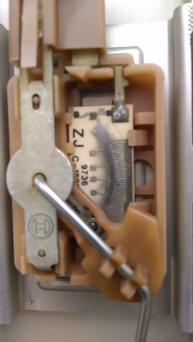

Assuming 5 markers on the sending unit equal E, 1/4, 1/2, 3/4, F. All I did was turn key on, put ground wire to a terminal and key on, record gauge indication.
Last edited:
UPDATE:
ALL MEASUREMENTS WERE WITH PUMP ASSEMBLY DISCONNECTED FROM BODY HARNESS & KOEO
*Pin 6 ground confirmed GOOD.
*Pin 3 voltage 5.16v
*Pin 4 no voltage.
Without a variable resister connected to the circuit you're going to need to back probe the connector with the fuel pump assembly connected. (closed loop)
I sometimes use paper clips, needles or thin pieces of stiff wire.
__ fuel pump module plug __
Pin 1 - (12 volts) A141 16DG/WT FUEL PUMP RELAY OUTPUT
Pin 3 - (5 volts ) K226 20DB/LG FUEL LEVEL SENSOR SIGNAL
Pin 4 - (.4 to 9 volts) K167 20BR/YL SENSOR GROUND (variable resister signal)
Pin 6 - (ground) Z1 16BK GROUND
Obviously Pin 4 can't be measured open loop (plug disconnected) unless it is connected to a variable resister.
You could place a var resister between pin 3 and pin 4 ... to test the fuel gauge ...
In order to test the fuel ga. sending unit it needs to be connected with the module plug (closed loop)
Or you could remove it and jumper it over to pin 3 and pin 4, using jumper wires.
I don't know if pin 6 (or pin 1) needs to be connected to use pin 3 and pin 4 ... I think 12 volt Pos+ and Neg GND are primarily used for the fuel pump. (separate from the sensor circuit)
Last edited:
Fuel Gauge Operation:
A constant input voltage source of about 12 volts (battery voltage) is supplied to the resistor track on the fuel gauge sending unit. This is fed directly from the Powertrain Control Module (PCM) via the Signal circuit.
I guess I was wrong about the connector ... From Sidewinders information ... 12 volts is also used for the sensor unit.
My FSM doesn't seem to have that information anywhere ... All my FSM shows is the PCM sends a 5 volt signal to the fuel gauge sensor unit which return a signal back to the PCM. I think some of the later FSM years were revised and have other information included or my set is incomplete for earlier years 98/99
Most of the diagnostics and troubshooting information in the FSM is for use with a DRB-III scan tool ... (perhaps the price has come down Chrysler hand held scan tool use to cost around ~$6,000.00 for a new one)
Last edited:
This is what my 98 FSM shows for pin outs.
CAV CIRCUIT FUNCTION
1 A141 16DG/WT FUEL PUMP FEED
2 - -
3 K226 20DB/LG FUEL LEVEL SENSOR
4 K167 20BR/YL FUEL RETURN SENSOR
5 - -
6 Z1 16BK GROUND
I could not find any information regarding how the fuel sensor operates other than the PCM sends a 5 volt signal to the fuel ga. sending unit which returns a signal back to the PCM.
But makes sense now knowing the voltage signal varies from .6 to 8.6 volts ...
Last edited:
Sidewinder CC
NAXJA Forum User
- Location
- Canton, Michigan
This is what my 98 FSM shows for pin outs.
CAV CIRCUIT FUNCTION
1 A141 16DG/WT FUEL PUMP FEED
2 - -
3 K226 20DB/LG FUEL LEVEL SENSOR
4 K167 20BR/YL FUEL RETURN SENSOR
5 - -
6 Z1 16BK GROUND
I could not find any information regarding how the fuel sensor operates other than the PCM sends a 5 volt signal to the fuel ga. sending unit which returns a signal back to the PCM.
But makes sense now knowing the voltage signal varies from .6 to 8.6 volts ...
wsxjeep,
Where did you find that 5 volts is used in the signal circuit? I couldn't find this reference anywhere.
It could be that in pre-'99 XJ's 5 volts was used as the signal and that after '98 12 volts was used.
I measured the voltage at pin 3, using pin 6 as ground, on my '99 and found that near battery voltage was present (11.40 volts).
VAcherokee is seeing 5.16 volts at pin 3, which is typical of sensor reference voltage.
Similar threads
- Replies
- 27
- Views
- 908
- Replies
- 17
- Views
- 3K