Dr. Jeckel
NAXJA Forum User
- Location
- Amarillo, Texas
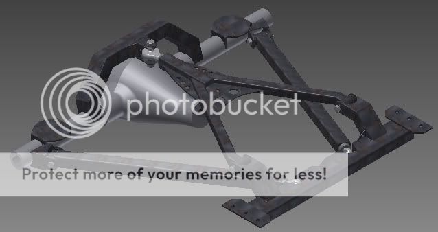
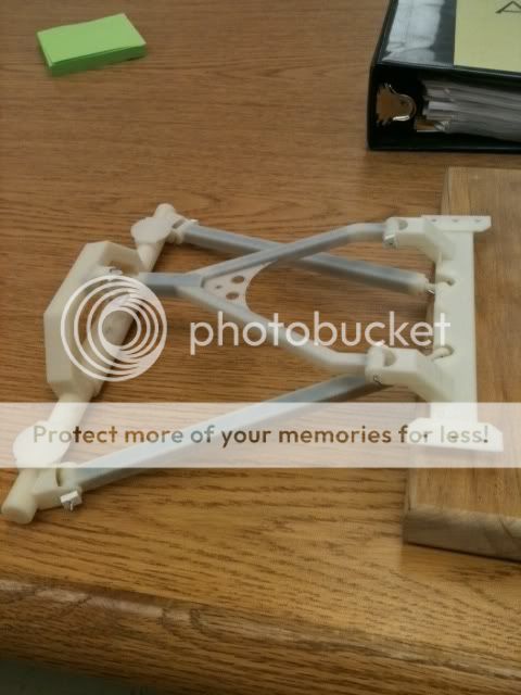
I designed a wishbone 3-link and double triangulated 4 link for my xj cherokee using autocad(intial design) and Inventor software to model it. My cherokee has a 6" lift and 33" tires. We have a 3D modeler where I work so I made a model of the 3 link just to kind of test out my idea. It was before I made a couple tweaks to the design.
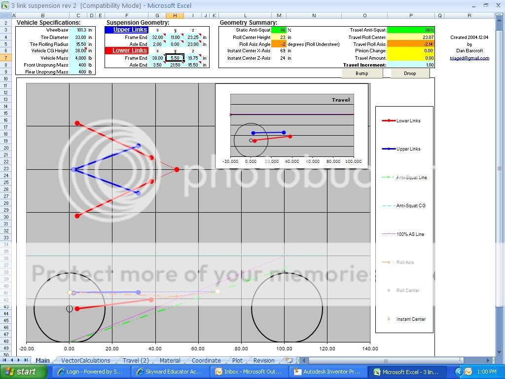
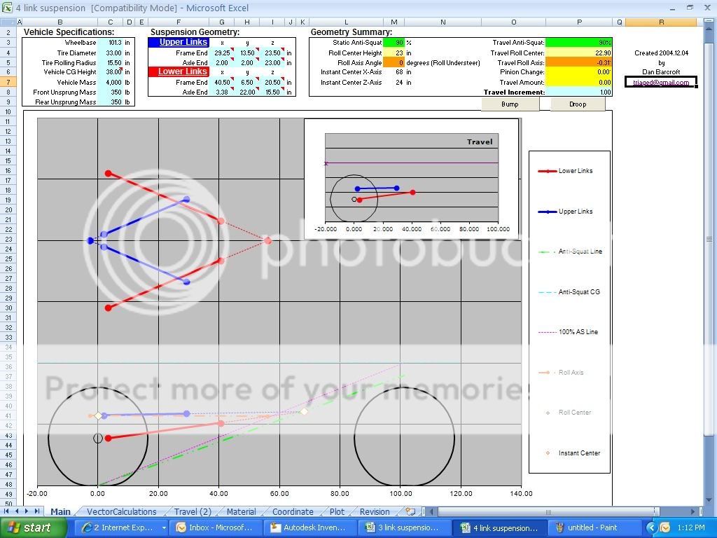
I read ALOT(until my head hurt...took a break and read some), looked at a bunch of pictures of linked suspensions and think I KIND OF understand the basics involved with using the calculator and what the various items mean and affect.
I decided to just keep my leaf springs for the time being and just do a truss with an anti-wrap bar, which I'll post some actual pics up later once I finish it, but wanted to put up the pictures of the link designs and the calculator numbers for those that might be interested in doing something similar.
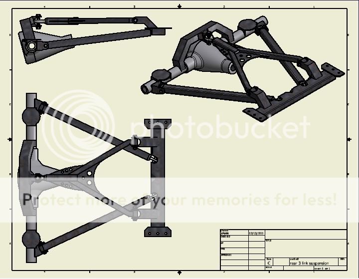
The crossmember mounts to the underside of the unibody and the upper link mounts are designed to sit about 1/2" below the floor. This will require the floor to be clearenced progressively to about 2-3" near the center of the upper links for up travel.
Anyway, I know it's not an actual build but I know that I like looking at pictures for ideas and thought that it might give someone else ideas.
Here are the pics for the 3 link:
Lowers would be 2" square tube .25 wall thickness with 7/8" heims and bushings. Uppers would be 1-1/2" .120 wall sleeved with 1.25" .120 wall that merg into a 2" square tube .25 wall thickness and use a 1.25" heim and bushings.
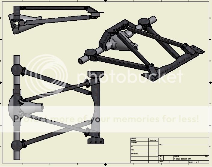
Here are the pics for the 4 link:
Lowers would be 2" square tube .25 wall thickness with 7/8" heims and bushings. Uppers would be 1-1/2" .120 wall sleeved with 1.25" .120 wall with 7/8" heims as well.

Maybe some day I'll actually put one of these ideas into practice, but until then I hope it helps someone else out when thinking of ideas.
James
I read ALOT(until my head hurt...took a break and read some), looked at a bunch of pictures of linked suspensions and think I KIND OF understand the basics involved with using the calculator and what the various items mean and affect.
I decided to just keep my leaf springs for the time being and just do a truss with an anti-wrap bar, which I'll post some actual pics up later once I finish it, but wanted to put up the pictures of the link designs and the calculator numbers for those that might be interested in doing something similar.
The crossmember mounts to the underside of the unibody and the upper link mounts are designed to sit about 1/2" below the floor. This will require the floor to be clearenced progressively to about 2-3" near the center of the upper links for up travel.
Anyway, I know it's not an actual build but I know that I like looking at pictures for ideas and thought that it might give someone else ideas.
Here are the pics for the 3 link:
Lowers would be 2" square tube .25 wall thickness with 7/8" heims and bushings. Uppers would be 1-1/2" .120 wall sleeved with 1.25" .120 wall that merg into a 2" square tube .25 wall thickness and use a 1.25" heim and bushings.
Here are the pics for the 4 link:
Lowers would be 2" square tube .25 wall thickness with 7/8" heims and bushings. Uppers would be 1-1/2" .120 wall sleeved with 1.25" .120 wall with 7/8" heims as well.
Maybe some day I'll actually put one of these ideas into practice, but until then I hope it helps someone else out when thinking of ideas.
James
