• Welcome to the new NAXJA Forum! If your password does not work, please use "Forgot your password?" link on the log-in page. Please feel free to reach out to [email protected] if we can provide any assistance.

The Nail Salon

Really enjoying the build Dustin! I've got a trans cooler on order (went with a 11x7.5 B&M cooler). Also seeing how small that power steering cooler is really has me considering it...
 
Time for an update.

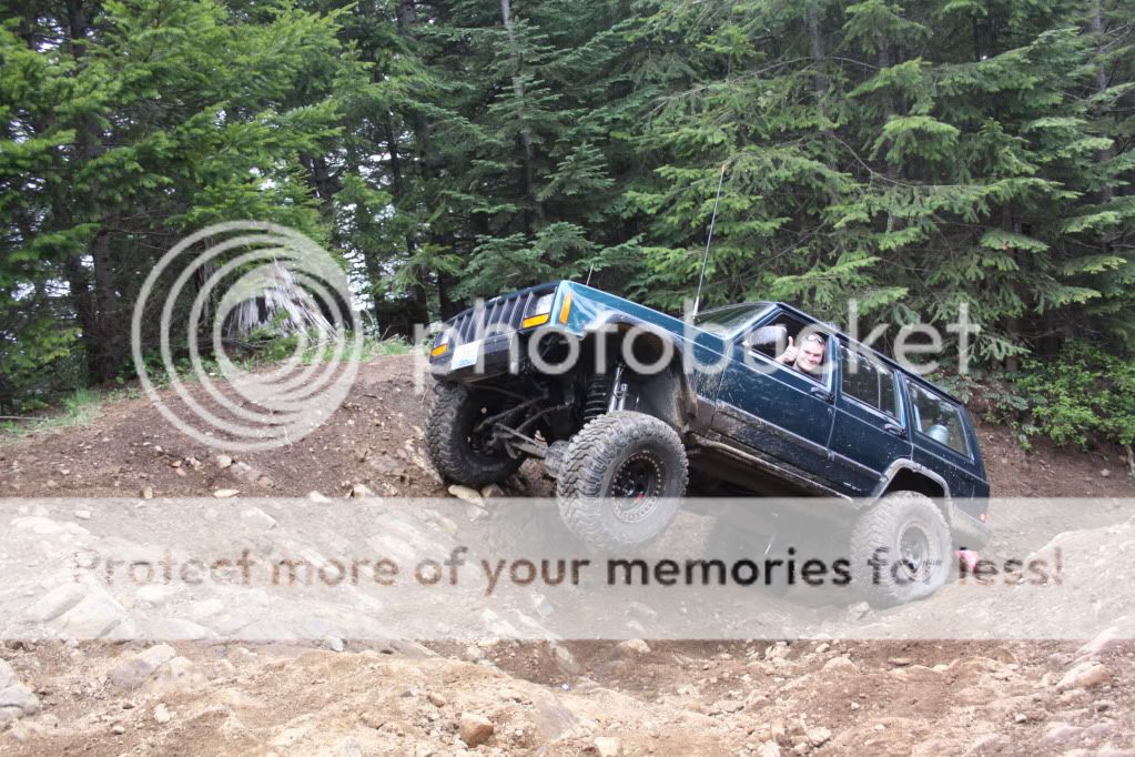
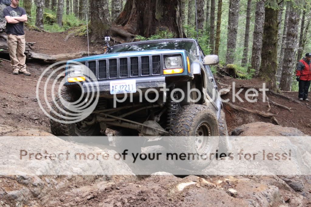
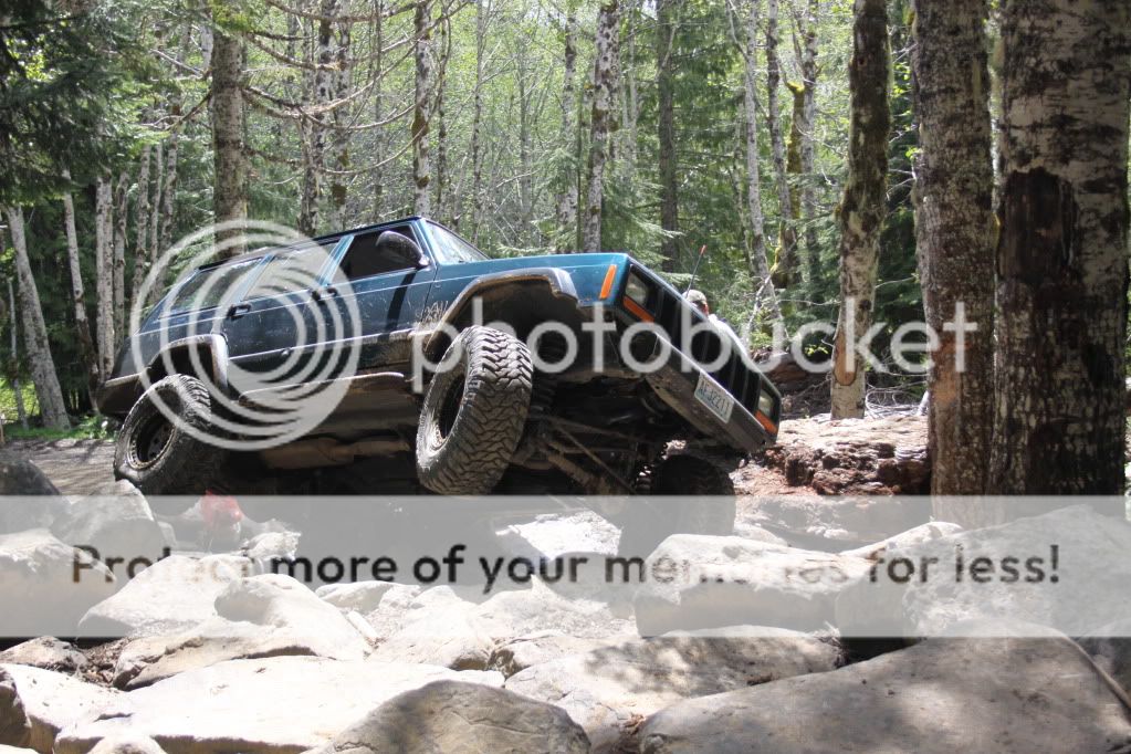
Took it to TSF for the first time Memorial Weekend. Photo cred goes to Alyssa.

IMG_4027.jpg


IMG_4064.jpg


IMG_4376.jpg


At first it still felt like a "new"rig, but by the end of the weekend I was flogging it just like the old one. Not sure if that's a good thing. Overall though it performed as well as I'd hoped.
 
I quickly found out "stubby" bumpers may look good, but they offer zero protection to the front end. Especially when your favorite game is Bumper Trucks.

P1070629.jpg


P1070628.jpg


Before I completely destroyed my front end anymore, I figured it was time to build a TORXfab 3.0 Winch Bumper.

Stopped by The Steel Yard in Portland for some materials. The Steel Yard always has a good selection of surplus steel, and their pricing is usually cheaper than the other yards. I got way more steel than I need for the project, but I'll use it up on future projects.
P1070625.jpg


Ideally I'd like to do something similar to this. Winch mounted behind the crossmember, great approach angle, and protection for the header panel.
ka61ir.jpg


However, a design like that just isn't feasible right now. I'd like to have this wrapped up by NWF, so I'll be building something similar to what Jeepforceone had. Just a basic winch bumper, and maybe low profile hoop for the Light Force's.

First task was stripping off the old stuff. Kenny, good news you can have your hookers back!
P1070627.jpg


Then I chose to remove the fender brackets. They don't do much, and just get in the way of the bumper brackets.
P1070630.jpg


Much more simple. I'll relocate the horns later.
P1070632.jpg


Dusted off the winch (Warn 9.5XP). It's still a bit dirty from NWF11.
P1070637.jpg


I mocked the winch into place, and got a rough measurement for how long the brackets needed to be. Then I began measuring for the layout of the mounting holes. Once I had my measurements I then transferred them to a piece of cardboard.
P1070640.jpg


With the lay out work done, I used a punch to test the holes locations.
P1070643.jpg


Before I could test fit, I had to remove the steering box bolts. I always incorporate them into he brackets for strength. The area around the box is always prone to cracking.
P1070645.jpg


The sheet metal around my lower bolt was already pulled in. Having the box bolted to 1/4" will be a peace of mind.
P1070646.jpg


With the box bolts removed, I could test fit my template. Success.
P1070649.jpg


I then transferd the measurements to the 6 x 1/4" flat bar. I rough cut two pieces to 24" knowing I can trim them down later.
P1070653.jpg
 
The OEM bolts are a 10mm metric, which come out to roughly a 25/64. I up the drill size just to give a little room for adjustment. In this case I drilled the 10mm holes out to a 13/32, and the 7/16 steering box bolts out to a 29/64.
P1070656.jpg


Holes drilled, and a quick counter sink to debur them.
P1070657.jpg


Completed brackets for now. They'll get cut down some more later.
P1070658.jpg


Spent some more time with CAD (cardboard aided design), and made some front cross member tie ins.
P1070663.jpg


$18 later I had all new hardware.
P1070665.jpg


Passenger side complete. I was surprised to find the passenger side on late models already are drilled for the steering box holes that are on the drivers side. Kind of nice being able to use symmetrical brackets.
P1070666.jpg


Front tie ins. I got these tacked together, but ran out of wire half way through welding.
P1070667.jpg


Layout work on the brackets is always tedious, so I'm glad to have that out of the way. I'll hopefully be able to work on this a little each day this week, with the shooting paint next weekend. :eek:
 
Do it how i did my jeep. it dosnt take much longer. Youneed to drop about 1.5-2"s to be safe then cut the crossmember untill the winch fits and build bumper.
 
Then I chose to remove the fender brackets. They don't do much, and just get in the way of the bumper brackets.
P1070630.jpg


Dustin your bumper looks like it's coming along and I suspect it's going to be great.
I would recommend that you reconsider removing the fender brackets for good. I took my driver side off because it was mangled in the accident that the previous owner was in. I always thought they don’t do much, but after having them off for a couple years I wish I had a straight one to put back on. Keep in mind my fender was damaged in the accident also, but the drivers fender seems to bend or flex every time we go out. I know that if that fender support was still there it would be much stronger because my passenger side doesn’t flex at all. Just my two cents but I felt like I needed to tell you my experience. I'm off to :speepin:.
 
Do it how i did my jeep. it dosnt take much longer. Youneed to drop about 1.5-2"s to be safe then cut the crossmember untill the winch fits and build bumper.
Do you get an email alert when your picture's used? :D

Nice job on the bumper though. It's literally exactly what I want to do. I'll stick with the traditional design now, and then when I'm set up for tube I'll relocate it behind the cross member.

Just my two cents but I felt like I needed to tell you my experience.
I know exactly what you mean. I noticed the same thing on Jeepforceone, but it wasn't a big deal for me. Maybe I'll drill a hole in the brackets for the fender support bolt, and add them on later if it's a big deal.
 
Had a little bit of time tonight to make some more progress. Tonight's objective was making the shackle mounts.

Take a chunk of 3/4" plate. Cut two pieces to 2.5".
P1070672.jpg


After a lot more cutting.
P1070674.jpg


Chuck them up on the drill press, set your RPM's, and let the chips fly.
P1070679.jpg


Completed mounts. These will not only get welded to the face of the bumper, but also directly to the frame brackets as well.
P1070681.jpg


Test fit with a 3/4 shackle.
P1070682.jpg


Picking up some wire tomorrow, and then it's fab time all day.
 
Great progress man. Cant wait to see how it turns out!
 
Picked up a new 10lb spool of wire. I tried welding the front tie-ins with my spare flux core spool, and gave up immediately. It's so nice to be back on gas.
P1070683.jpg


Got the front tie-ins welded up.
P1070684.jpg


Then it was time to move onto the main tube. Rather than butt welding the 4x2 to the frame brackets, I like to notch it to slide over the brackets. Cut lines laid out.
P1070689.jpg


After some time with the grinder I had my notches completed.
P1070691.jpg


Test fit.
P1070692.jpg


Good fit.
P1070693.jpg


Then I began laying out the cut lines for the shackle mounts to slide through the 4x2.
P1070695.jpg


Completed.
P1070696.jpg


The shackle mounts will be welded to the face of the 4x2, and then to the frame brackets as well.
P1070698.jpg


Third task was notching the 4x2 for the winch plate. I wanted the winch to sit 2" below the top of the bumper, so I did a quick lay out.
P1070702.jpg


After some quality grinder time, I had separation.
P1070705.jpg


Test fit. It's starting to look like something.
P1070708.jpg


With the winch plate notch completed, I cut some .188" plate for the winch plate.
P1070711.jpg


I still need to trim the brackets down an inch to move the winch plate back.
P1070712-1.jpg


Finished off the night by drilling the winch plate to Warn's 10x4.5 bolt pattern. I guess I could just burn all this on and go to NWF with a stubby winch mount. We'll see how much more I can get done in the next few days.
 
Only .188 for the winch plate? Figured you'd go for .250.....
I like your train of thought on the shackle mounts, that's going to be super strong....
 
Tuesday's progress:

Using a straight edge, I mocked up how far I wanted to bend the ends of the 4x2 backward.
P1070714.jpg


Once I settled on a position, I transferred the angle to the workbench. Using a protractor, I determined the angle I needed was 37 degrees. This meant I'd mark 18.5 degrees on either side of my bend location.
P1070718.jpg


Measure twice, cut once.
P1070719.jpg


After I finished cutting out the angle I used a torch to heat up the metal to help bend it into place.
P1070722.jpg


With the ends bent, I cut the ends to length.
P1070728.jpg


Next step was tapering the ends upward. This helps with clearance, and I think it looks much better than a flat piece of rectangular tube.
P1070732.jpg


Normally, I just cut the piece clean off and cap it with some 2" flat bar. This time I thought I'd try and splice the tube back together.
P1070738.jpg


Clamped the tube back together, and tacked it in place.
P1070734.jpg


Complete. It's a bit more to cut, but it's going to be a lot easier to blend back in verses the flat bar route.
P1070739.jpg
 
Any plans to extend the ends back under the body under the fenders? ("side protection")
 
Little bit of progress today. Used some 2x1x.120 for the end pieces. Got them cut down, ends capped, and the angles matched.
P1070750.jpg


I chose to orient them this way for the exact reason Andy pointed out above. The edge gives a place for a hi-lift to grab on to if needed. Doesn't really flow too well, but whatever. Also, this was taken before trimming the brackets, so it sits an inch back from this picture.
P1070746.jpg


Capped the ends of the main tube.
P1070747.jpg


Shed some weight off the brackets. They're 6lbs each if anyone cares.
P1070752.jpg
P1070752.jpg


Pretty much ready to start tacking everything together, and adding some filler plates.
 
Last edited:
Back
Top