• Welcome to the new NAXJA Forum! If your password does not work, please use "Forgot your password?" link on the log-in page. Please feel free to reach out to [email protected] if we can provide any assistance.

Project Downward Spiral

Some updates:
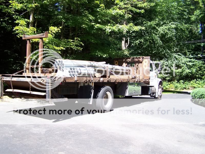
Some steel arrived this past week (no... the pipe isn't mine :laugh2: )

Steel_Arrival_7-16-08.jpg


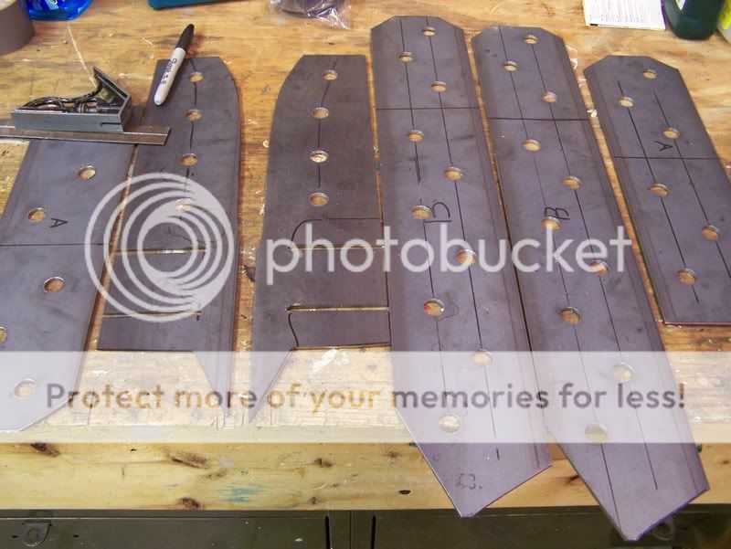
I made some templates and then cut up some 1/8" steel plate to make some really long fish plates to enforce the replacement rail joint. Two of the plates are also to go down the side to the location of where the front of the leaf spring used to mount. I've still got to make some for the inner side of the rail to enforce where the links will mount.

FrameSupportBraces.jpg


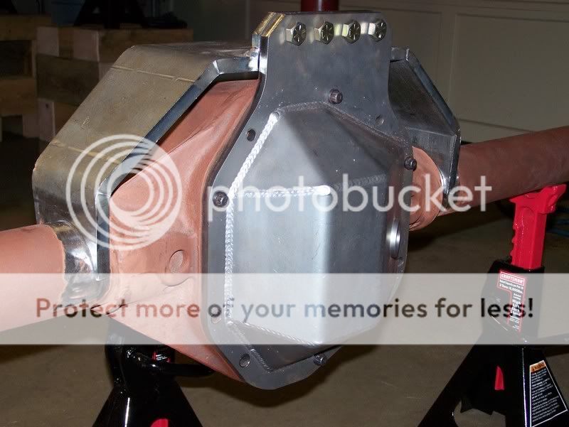
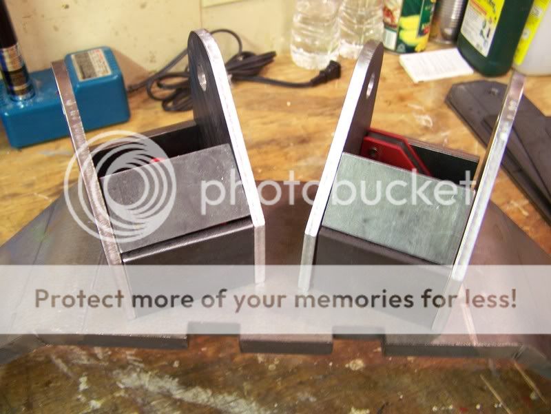
After numerous calculations I couldn't get the supplied brackets that came with the BTF D60 rear truss system for the upper link mounts on the axle side to work. They really needed to be 1.5" taller.
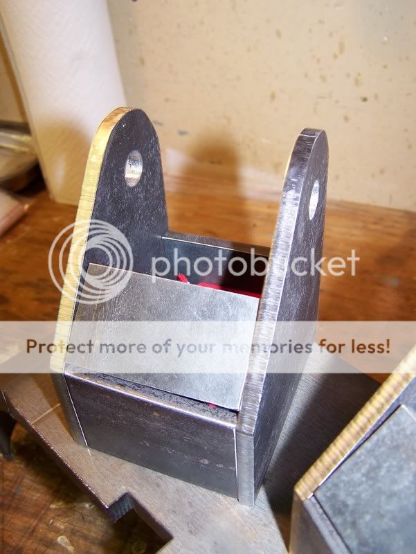
So I made some of my own (no way in hell I'm gonna pay $5+ for a simple bracket). Everything below is 1/4".
I've probably got way to much time into these, but I'm sure they'll hold up! I made some braces for between them, they will also probably get gussets on the outside. Not welded yet, just sitting together with magnets.

UpperLinkAxleSidePair.jpg


UpperLinkAxleSideSingle.jpg


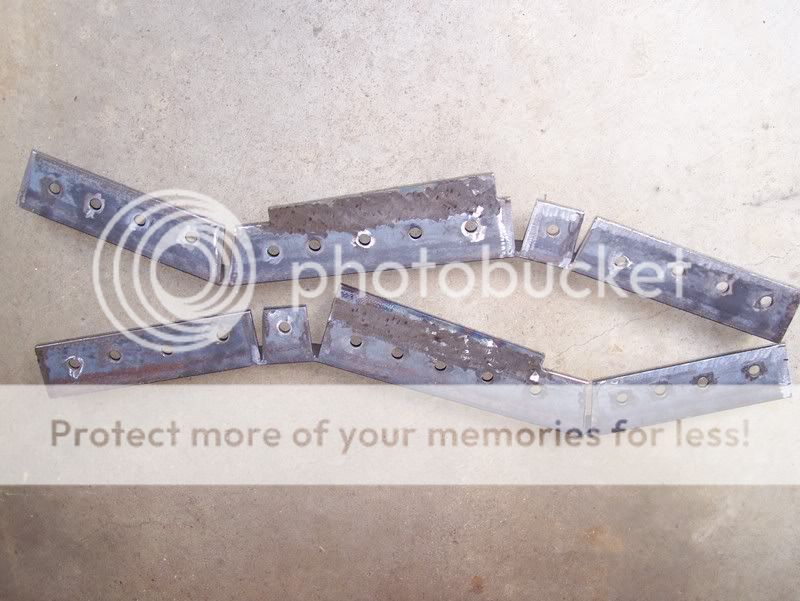
I also measured and made up some frame side brackets for the rear links. Who says the average DIY'er can't have fancy slotted brackets? Just gotta make them. :thumbup:

Lowers (upside down):

LowerLinkBracket.jpg


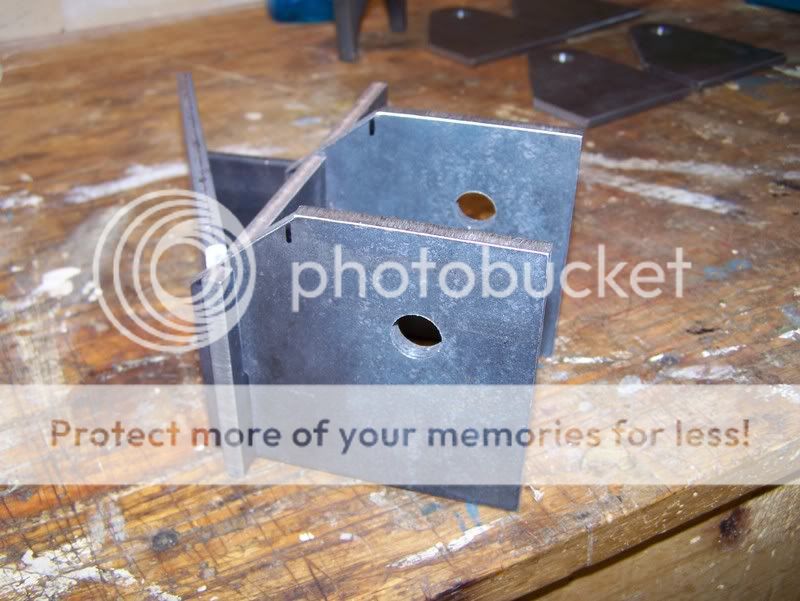
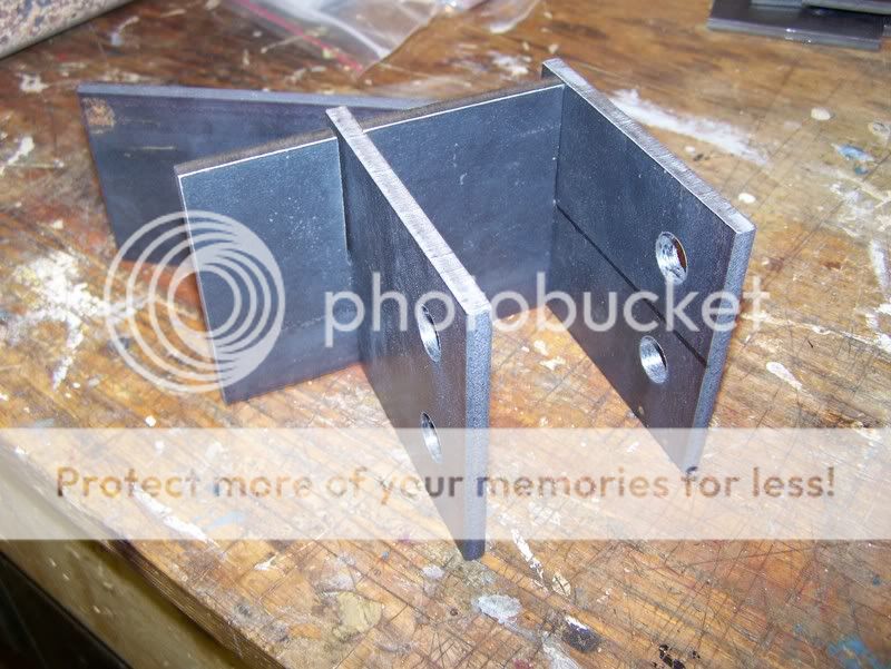
Uppers, two holes in these as it leaves room for one of two different 4 link setups to figure out what works best.

UpperLinkBracket.jpg


That's it for now. I've still got to make the 1/8" plates that will brace the inner side of the unibody rail so the link brackets don't tear off. I'm thinking that plating the unibody with 1/8" and welding the brackets to that should be fine. Right? :dunno:

As for links, the plan is as follows:
2-5/8", 1.25" shank Currie Johnny Joint on one end of the link, and a welded greaseable bushing on the other for all links.
Lowers: 2"x.500" wall or 2"x.250" wall
Uppers: 1.75"x.375wall
 
Last edited:
JeepFreak21 said:
What tools did you use for those fancy slotted brackets?
cool.gif

Billy
A Sharpie, ruler, bandsaw, bench grinder, and a Bridgeport. However, the a drill press would have done the same thing the Bridgeport did in this case as it only drilled the holes for the slot ends and the arm mounts. I have access to it, so why not, right? :laugh3:
 
RCman said:
That's it for now. I've still got to make the 1/8" plates that will brace the inner side of the unibody rail so the link brackets don't tear off. I'm thinking that plating the unibody with 1/8" and welding the brackets to that should be fine. Right? :dunno:

After some quick discussion on another forum, I've answered this question myself. I'll be bending up and using some 3x3x3/16" angle instead.
 
RCman said:
As for links, the plan is as follows:
2-5/8", 1.25" shank Currie Johnny Joint on one end of the link, and a welded greaseable bushing on the other for all links.
Lowers: 2"x.500" wall or 2"x.250" wall
Uppers: 1.75"x.375wall

Plan changed.
After hearing rumors that the Johnny Joint was forged in China (n) , I couldn't have that.
Called Summit Machine and I've now got some flex joints, tube adapters, jam nuts, and poly bushings on order from them. Great to deal with, btw.

Also, the tubing size has been changed. The now up to date plan is to run
Lowers: 2" x 0.375" wall
Uppers: 1.75" x 0.25" wall

Also did some work on the XJ itself (rather than ordering parts), but updates on that later.
 
Alright… small updates.

Got the Jeep all raised up and at what should be ride right. It might increase an inch or so, but I’ve got to get some axles mocked up underneath to know for sure.

Raise_Up.jpg


Next I pulled out the front axle. I don’t know why I fought with the bolts on the control arms for about 30min or so as I’m not using them. It then dawned on me that I indeed have a sawzall. :D Finished getting her out in about 15min from that point.

FrontAxleOut.jpg


Then I went back to the rear of the Jeep and got the re-enforcement plates for the replacement unibody rails welded in. I forgot to snap a picture of that, I’ll do that later. I was planning on working more on it tonight, but I got stuck replacing a u-joint in the driveshaft of my Silverado instead. :(
 
I got some requests to post some pictures of my bender. I built this using the gottrikes.com plans. That’s a 240degree, 1.75, 6” radius die.

Collapsed for storage:

Bender_Collapsed.jpg


Extended out about 1/2 way bending air:

Bender_HalfExtended.jpg
 
thanks for the bender picks. You are getting me excited to build mine.
 
I see you're in MA/VT, where's the bender located? I wouldn't mind checking it out to compare to a JD Model 3.

I'd narrowed down my bender options to either the Model 3 or building one of those. I've had the opportunity to use an air/hydraulic powered Model 3 a few times and loved it, but the Gottrikes looks pretty decent for less money (if you don't count time/labor...) Could be a fun project anyway though.

And what are you using for a band saw if you don't mind me asking?

Been watching you change your mind over your XJ on a couple different boards, but the progress is looking good so far. Can't wait to see what you end up with.
 
I enjoy seeing this build progress and the quality parts being used in it!

Thanks for sharing it with us!
 
I used nearly the same bender arrangement for my exo. Much nicer than my full-manual model 3...I think this one had a ProTools die in it. I like the vertical arrangement better than the horizontal too.

DSC02714Medium.JPG
 
nhrocker said:
I see you're in MA/VT, where's the bender located? I wouldn't mind checking it out to compare to a JD Model 3.
Bender is in at my place in north central MA, if you want to come take a peak shoot me a PM. I'd be glad to show you some time.
nhrocker said:
And what are you using for a band saw if you don't mind me asking?
Haha... you wouldn't want to know. Lets just say I'm VERY lucky to be able to have access to it and I could build my XJ twice for what it cost. Really, I havn't used it much for anything I couldn't do with the tools I have at my house, (that goes for the Bridgeport too), they are just easier to use.
nhrocker said:
Been watching you change your mind over your XJ on a couple different boards, but the progress is looking good so far. Can't wait to see what you end up with.
Ya... I think I've finally got the direction in which I'm going down now. The biggest thing in my way is money. I cain't wait to drive it, but building it is a heck of a lot of fun too!
 
Last edited:
XJ_ranger said:
I enjoy seeing this build progress and the quality parts being used in it!

Thanks for sharing it with us!
No problem! Thanks for reading. If you find anything to critique me on.... speak up please! :)
vetteboy said:
I used nearly the same bender arrangement for my exo. Much nicer than my full-manual model 3...I think this one had a ProTools die in it. I like the vertical arrangement better than the horizontal too.
http://www.pirate4x4.com/forum/gallery/files/3/1/6/2/1/DSC02714Medium.JPG
Yup, mine uses a ProTools die a well. After looking around for a bender I knew I wanted an air/hydro setup and this was really the only way I could do that without spending a ton. I'm very happy with the results.
 
Some progress tonight:
I had sandblasted the front knuckles, front brake brackets, front spindles, and all four hubs prior to tonight, so they only needed to be primed.
Not bad for almost 30+ year old parts, huh?

AxlePartsPrimed.jpg


I also got the rear BTF truss mocked up and the tab that integrates the cover welded on. I primed the parts of the truss and the axle that once welded I couldn't get to (not shown). Once the primer is dry I'll shot some paint in those areas and hopefully tomorrow get the truss fixed to the axle permanently.

Rear_Truss_Mockup.jpg


It is tough to get much at night after getting home late from work, but progress is progress.
 
It's looking great, keep up the good work. I think you'll be happy with that low profile trus, nice & beffy!
 
Not much to report on tonight it is hard to get much work down (and not create dust) while you're trying to get paint to dry nicely. Some work was down, but nothing worth typing.

However, the disc brakes for the rear are in and it gives me something else to paint :)

D60_Rear_Discs.jpg


Oh, and in case anyone is wondering the axles are going to get the Rustoleum Hammered Bronze treatment. Everything else will be black, red, or white depending on where it is going. I know 99% of you don't care, but ya...
 
still looks awesome. i can't wait to see the finished product. i'd say we should wheel sometime when it's done but anywhere i could make it you'd be bored after how built yours is going to be :yelclap:
 
asp387 said:
still looks awesome. i can't wait to see the finished product. i'd say we should wheel sometime when it's done but anywhere i could make it you'd be bored after how built yours is going to be :yelclap:

Ahh, we'll have to figure something out. I'm sure there will some some "less aggressive" shakedown runs. :)
 
Progress was made on the rear inner braces where the link mounts will go this weekend.
I knew it would take awhile to get the angle iron bent up and in shape to fit the rails nicely, but I had no idea I'd spend so much time on them.

Anyway, got them to hug the rails very well after a long time cutting, heating, bending, and drilling.

InnerRearBracesContour.jpg


Then I wanted to make sure the link brackets would fit good on the new steel so before I burned them on I held them up and ran into a small issue.

InnerBracesRev1.jpg


Now I know that I could have probably gotten away with that being as I am going to put braces on the back side of the brackets, but just knowing that the gap was there would drive me nuts. So off they came again and I spent some time cutting welding and smoothing in some "extensions" for that area to fill in the void. Had I known that I was going to add these I would have drilled the holes for the rosettes higher up... oh well.

Much better.

InnerBracesRev2.jpg


Here's a shot of them sitting on the floor before clamping them back in place for welding. Almost hard to believe that they used to be a straight piece of 3x3x3/16" angle. What the picture doesn't really show is that they arn't straight in the other direct either, there is a curve inward as they go toward the back. There is also a notch on each one to clear the "body mount" where the front leaf spring mount used to be.

InnerBracesFloor.jpg


I did get them partially welded on before I took a break for dinner... that was a bad idea cause I just didn't want to get started again tonight. I'll finish welding them tomorrow night hopefully. Now time for a shower.
 
Back
Top