• Welcome to the new NAXJA Forum! If your password does not work, please use "Forgot your password?" link on the log-in page. Please feel free to reach out to [email protected] if we can provide any assistance.

Benz diesel in a XJ speedometer & TC lockup

diesel-xj

NAXJA Forum User
Location
texas
hello all, I have the Mercedes jeep up and running, but a few little items to sort out. This is/was a 1996 2 door 2wd xj that had a 4.0l and an AW4 automatic. Stock gears, axles, etc. Now it has a 1976 MB 300d NA 5 cyl engine, still using the AW-4
The engine runs well. I was concerned that I would not have auto shift, but it does work in auto.

For sensors; all the intake manifold sensors are hooked up but not installed in the manifold so they are just sensing under the hood conditions. 1 O2 sensor is hooked up, Crank position/input speed sensor hooked up. Output speed sensor hooked up, TV cable hooked up. The only loose wires are the injector harness I cut. This was a SE model with idiot lights. So I put in aftermarket oil pressure and water temp, and an electric fan.
The problems for now are I lost the speedo after my 2nd short test drive. I have not checked the OSS sensor yet. Also I am not getting TC lockup at all.
I tried hooking up the throttle position sensor to actually move with the throttle to see if that would help the TC lockup, with the TPS hooked up and working, it made the 1-2 shift all messed up. The 1-2 shift was very late, then the slightest throttle pedal movement caused a downshift, I could not get into 3rd. I now have the TPS hooked up, but not being moved, so it is always sensing idle. This seems to work the best. I get a good 1,2,3,4 shift, but not TC lock up. Also I unhooked the TV cable and this smoothed out the 1-2 shift a bunch.

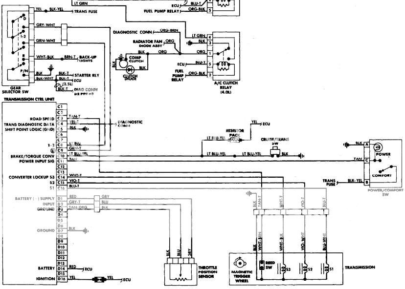
So I am looking for help with the speedo signal and the TC lockup. As a last resort I am thinking to put in a lockup toggle switch. I have not tried this yet. I believe the lockup is the purple/white and white/black.
I checked these 2 wires with ignition on trans in drive engine not running. Neither of these 2 wires has power.
Are these the correct wires for TC lockup in a '96???

thanks
 
For speedo, there is a couple companies that make GPS speedos. So more accurate than stock. Since you have idiot light IP Maybe install an aftermarket set of gauges? As for TC lockup, did you check the brake switch? Either way, I would install a TC lockup switch. Also helps in offroading.
 
Thanks I did not check the brake switch, good call on that. Thanks. This is a 2wd highway MPG vehicle. If that does not work out, then it will get put out in the country, but a 4wd conversion is not in the cards for this chassis.
There are 2 brake switches correct? one for the brake light, and where does the other one go? TCU?

thanks
 
I run a TC toggle switch and it works great. That way I can just lock it up whenever I want. there is a great article on google somewhere. I would just google XJ TC lockup switch. something easy will comeup.

Ive never locked the TC offroading. Id love to see someone who has actually done so chime in under what conditions they do so, not just speculation.
 
I looked in my transmission manual, but the manual is for a my '98's; and the '96 is different wire colors I think. So that will be cool if it is just a toggle switch. Any idea on how many amps the switch needs to be? I want to put a little push button in the right side of the shifter T-handle.
 
ok I got the wire colors yellow to white/black. I need to check the brake switch first

thanks

any help on getting the speedo to work?
 
ok I got the wire colors yellow to white/black. I need to check the brake switch first

thanks

any help on getting the speedo to work?

The 1996 speedometer gets its signal directly from the speed sensor. It just needs to be wired into the instrument cluster. The 18 gauge White/Orange Stripe wire from the sensor should wire into cavity A5(LHD) or B6(RHD) of the main connector on the cluster.

The connector for the sensor:
Cavity 1 - 18 Gauge - White/Orange Stripe - Vehicle Speed Sensor Signal
Cavity 2 - 18 Gauge - Black/Light Blue Stripe - Sensor Ground
Cavity 3 - 18 Gauge - Orange - 8 volt supply
 
thanks a lot for the speedo info I hope I can check it this weekend. I have been looking for brake switch adjustment procedure and have not been able to find a adjustment procedure for the upper brake switch. I did find a schematic that says brake released switch closed. So that means continuity with no brakes. Is there a manual that has this brake switch adjustment? I googled and only found info on the brake light switch.

If it is not raining to much tomorrow I will try and get some of this trouble shooting done. The jeep is drivable like it is, but it could be much better.
Overall I am pretty happy to have a diesel jeep. I already have the next conversion in the planning stages. I am just not sure if I want to tear apart a perfectly running '01 that still gets a solid 21mpg highway.
most of the problems I have had with this conversion were caused by the fact that I started with a $100 POS non runner '96 xj that had been sitting for 6 or 7 years. the engine went in with only a few normal problems. Then I had to put in new brakes, new tires, new lights, it still needs some front suspension work, shocks, and tie rods. So it would pay to start with a nicer starter jeep, I wish I could find a nice one with only a blown engine. I am not in a huge hurry,

Thanks again for the speedo info
 
thanks a lot for the speedo info I hope I can check it this weekend. I have been looking for brake switch adjustment procedure and have not been able to find a adjustment procedure for the upper brake switch. I did find a schematic that says brake released switch closed. So that means continuity with no brakes. Is there a manual that has this brake switch adjustment? I googled and only found info on the brake light switch.

Do you mean the switch under the brake pedal? My method was to buy a new one for $17. I tried adjusting several of those, but I always ended up breaking the plunger. Also, I am opening normally open on the diagram I have, but I do not know which brake switch your Jeep has.(With or without cruise control.)

I also show the brake pressure warning indicator switch as being normally open.
 
ok it finally stopped raining and dried up a bit. this is what I got under the car.
Engine running transmission in drive wheels off the ground and spinning.
disconnected the plug from the tail housing. in the plug orange to black/blue= 2.2 volts. on the transmission Wht/orange to grnd, 0 volts and open ohms no fluctuation. This is on a digital meter
I found one blown 20 amp fuse in the power dist panel under the hood. my p-dist cover does not list a function for this fuse.

ON the brake switch. I only have the one switch on the brake pedal arm. I did not check it, because the brake lights are working. so I assume that the switch is good, maybe not the wires from the switch, but at least the brake lights work.

I still need to check all the fuses under the driver foot well. but that is what I got so far.
 
so you think that if I go from 2.2vdc on the orange wire to 8vdc, the speedo will work? Also I bought a new cheep analog meter, I was going to try and check for a OSS speed out signal again. This will be a resistance fluctuation correct?
 
The TCU requires all sensors on the transmission are connected (iss, oss, and nss) and that the throttle position and break switch are connected and functional. The TV valve really should remain connected if possible. I hooked a 97+ tcu up to a 93 without any data lines of any kind, and the speedo is driven solely off of the speedo gear in the transfercase and the ECU. I could see you easily swapping a cable driven speedo out of an older jeep since you have a 96.
 
I am really hoping to not have to pull the dash apart. So much so that I am wanting to find the wire color that feeds the speed signal to the cluster. I just got the little solid state voltage regulator I will solder it up tonight with a heat sink, and see if I can't put it in tomorrow
To me it is strange that the transmission shifts at all on its own The shift points are not ideal, but it is driveable as is.
I do have I think all the sensors hooked up. some don't show actual conditions, but they are all hooked up.
Does anyone have any ideas why the OSS orange wire only has 2.2 vdc Does the OSS get its power from the TCU?
 
i got 2.2vdc at the OSS harness plug on the orange wire to the black wire . I am not sure if I am getting conflicting info or not. from post 7 on page 1 of this thread, I understood that the orange wire should be 8vdc.
my OSS is as described in post 7. no twisted wires, I have a Orange/blk wire, a black wire and a orange wire. 3 wires in the tailhousing, what I call the OSS.
I thought the orange/blk wire ( speed signal out ) on the trans side of the actual OSS sensor would be a variable resistor as well. I tried checking if for resistance with the engine running and trans in gear with rear wheels spinning. but I was using a digital meter, and I got nothing.
I bought a cheap analog meter, and I will check the OSS for a pulse resistance turning the wheels by hand engine off, and see, I think I should get a resistance variation with hand turning? If I understand correctly.
Then I plan on putting this little solid state voltage regulator in line with battery power and put that too the orange wire feeding the OSS, and see if I get the speedo back.
But if I am trying to figure out what went wrong or broke. and the orange wire feeding the OSS is supposed to have 8vdc and I have 2.2vdc. Where is that original 8vdc fed to the OSS from??????

thanks to all for your help so far.
 
I don't have a FSM for a 96 so I cant speak to the color. The TCU OSS (Output Speed Sensor) is separate from the VSS (Vehicle Speed Sensor). It looks like I was wrong about the OSS being a variable reluctor, its just a simple magnetic switch according to the diagram. The VSS is a Hall Effect (I'm pretty sure) and therefore requires the 8v or whatever someone else mentioned. The TCU is what I'm talking about. Here is a generic diagram of what is needed to make the transmission and lockup function. The TCU functions on a completely independent circuit from the speedometer, and does not require the diagnostic connection at C4.

TCU.jpg
 
thanks for the help so far. I got the trans to shift ok, If I need , I can work on a manual lockup for the TC at a later date, also I can worry about changing the shift points later.
I want to concentrate in the speedometer. I got the little solid state Voltage regulator. I have pulled the cluster from the dash. There are no pin#'s on either the connector or the socket. I did find a screw on the electric tape on the cluster that reads " SP " I traced this to a pin on the connector. Is this the speedometer signal input? see picture.
So if I want to wire this up completely independent. I cut the 3 wires at the sender on the transmission. I put +8vdc to the orange wire, 12 negative ground goes to the blk/blu? and the wht/orange runs all the way to the cluster, and connects to the " SP " screw? Does that sound correct??? What is the purpose or difference between vehicle 12volt negative, and sender ground. What should I do about grounding the cluster?
At present the whole cluster is USELESS. I the fuel pump on the donor did not work, and I did not need it for the diesel, so I took the pump out, and the wires azre disconnected, So I lost the fuel gauge. I already have aftermarket Tachometer, water temp and oil pressure gauges. The cluster was only showing CEL, and oil pressure dummy light. So having the cluster not wired up to any thing is actually better for me as it get rid of that pesky CEL
I guess I will ground the cluster with a black wire
 
Ok I found the terminal #'s on the cluster plug on the wire end. I must look pretty funny with readers on over my bi-focals.
 
Back
Top