So... my 89 XJ has been getting horrible gas mileage and I figured out that the heater wire to the O2 has not been getting power. I traced it back to the starter relay. When I turn the key to "run" this wire on the starter relay should be hot(12v) correct ? I was trying to figure out which wire is going to the starter relay to "turn it on - the O2 heater wire" and put in my own universal relay as I have a few sitting around. Other option is to buy one for about 40 bucks. No time to go junkyarding either. On the starter relay theres 2 green wires - one goes to the starter solidnoid, the other green goes though a plug and then joins the first green wire. Theres one thin black/white wire which I think activates the starter solidnoid wire to start the rig.. which must be momentary only. Other than that.. just the cluster of hot "on" wires.
-
Welcome to the new NAXJA Forum! If your password does not work, please use "Forgot your password?" link on the log-in page. Please feel free to reach out to [email protected] if we can provide any assistance.
You are using an out of date browser. It may not display this or other websites correctly.
You should upgrade or use an alternative browser.
You should upgrade or use an alternative browser.
Renix XJ and bad starter relay.. I think.
- Thread starter dan89XJ
- Start date

xcm
NAXJA Forum User
- Location
- Southern Oregon
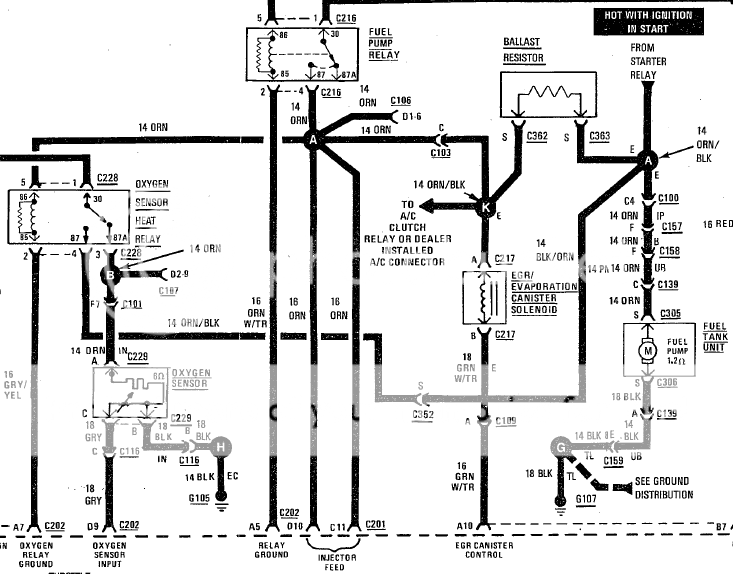
heres the wiring... from my 1990 renix anyways... check for broken wires... then check the relay itself for +12v and switched ground.


8Mud
NAXJA Forum User
- Location
- Central Germany
According to my Haynes manual the o2 gets the 12v power for the heating deal comes from the starter relay. From there it goes to the ballast resistor, to the o2 heater relay, then to the o2.
Nope, the wire coming from the oxygen sensor relay 87a pin is the one you want. Nothing at the starter relay that wires into the O2 sensor.
There is an out wire from the O2 sensor relay, 87 pin, tied into the fuel pump circuit, likely to be the three second prime, when the key is turned to start, but I sure don't now for certain, just a guess.
I've found that most times when the O2 heater circuit has an open circuit, it is because the sensor circuit harness that comes up the front of the motor to the fuel rail harness has fried on the front of the exhaust manifold (behind the power steering pump bracket/hard to see) and shorted. Or the wire breaks close to the O2 sensor. Your O2 relay may be toast, best to find the short before replacing it.
I could not find any voltage to my o2 heater relay plug. So I need to trace it to the next source of power from there. I thought it was the starter relay.. my haynes manual must be misleading and wire colors are the same. Ill try to get a copy of the diagram on here.
After studying the last diagram posted. Pin number 87 on the o2 heater relay does go to the starter relay. However, it does not clearly show me that its the wire powering the o2 sensor. Also pin number 86 is going back to the starter relay also though the ballast resistor as I am seeing on my XJ.
After studying the last diagram posted. Pin number 87 on the o2 heater relay does go to the starter relay. However, it does not clearly show me that its the wire powering the o2 sensor. Also pin number 86 is going back to the starter relay also though the ballast resistor as I am seeing on my XJ.
8Mud
NAXJA Forum User
- Location
- Central Germany
Main power "in" to most any old style standard relay is the 30 pin. The 30 pin on the O2 relay is a yellow wire at the socket, same circuit as the larger yellow wire to the ignition coil and the yellow wire to the alternator. The yellow wire is hot (or should be) when the ignition is in the run position.
You can test the larger yellow wire at the coil/ignition module with the key in the run position. If you don't get any power to the coil/ignition module, the problem is upstream (connector, splice, ignition switch or maybe even a fusible link). if you do get power to the coil, but no power to the 30 pin on the O2 relay, it may be the relay connector (it gets really funky under the relay block) a broken wire or the splice, the coil and alternator share with the O2 sensor in the harness.
There are some small differences in wiring from year to year, possible the 87 pin on your O2 sensor relay ties into the BAL pin on your starter relay somehow, but this is the fuel system and has nothing to do with the O2 sensor or power to the relay. For some reason the O2 sensor relay feeds current into the fuel pump circuit from the O2 relay, the reason eludes me, but as I mentioned it may be the 3 second prime for the fuel rail, when the key is first turned to run at the ignition switch.
Most all of the relays (Bosch) I've seen are numbered next to the pins, you may have to clean a little to read the pin number.
Ok, I'm getting a little frustrated here. Thanks for the help tho.. I did some more checking today. The yellow wire(30pin) is getting 12v when the key is turned on to run. Is this the wire that is suppose to power the o2 sensor ? I have verified the wire from the 87a pin to the o2 sensor is ineeded good and not broken. I have tested 87 pin to have a connection at the starter relay using the ohm on my volt meter.. so current can flow though there and is connected there.. like the wiring diagram shows. I have tried to test my relay and with a good known relay to see if the relay is switching. With the key on pin 30 gets 12v and pin 87a or 87a is not getting the 12v. However.. I am getting closed circuit readings with my volt meter from pin 30 to 87a with the key on or off. Also closed circuit readings from 87a and 87pin with the key on or off. Which is confusing me.
I have poked around some more.. and I think I have a bad ground. This is the 85 pin on the o2 heater relay which is gray/yellow and goes to the ecu. So.. I went under the dash and looked at the big plug going to the ECU, and I see the gray/yellow wiring going in there. So.. what Do I do now ? Is this gray/yellow wire grounded though the ECU box which is grounded somehow ?
Looks like I got it fixed !
I pulled the ecu box and took the plugs in/out.. they looked clean. I sanded the ecu box mount with some sandpaper thinking it'll promote better ground. Reinstalled the box. Tested the o2 heater relay and I had proper power everywhere and ground at the relay ground to the ecu. So, I'll be checking for better MPG now !
I pulled the ecu box and took the plugs in/out.. they looked clean. I sanded the ecu box mount with some sandpaper thinking it'll promote better ground. Reinstalled the box. Tested the o2 heater relay and I had proper power everywhere and ground at the relay ground to the ecu. So, I'll be checking for better MPG now !
Muad'Dib
NAXJA Forum User
- Location
- Bend, Oregon
I have been chasing a problem on my Jeep, and i thought it was an issue with 12v supply to the 02 Heater Relay. After chasing it around and around, i found its by design on my 90 to only give the orange wire 12v for 5 seconds after turning the key to on. Only after its started will it have a constant supply of 12v.
FWIW, it IS tied into the Starter relay. Its in the same circuit as the fuel pump ballast resistor. You can easily test this by pulling the connetor off of the Starter relay (the one near the battery terminal thats orange) and supply 12v to it. You can obviously hear the fuel pump running and if you test the 02 supply at the 02 sensor OR at the 02 relay you will also see voltage there. I can take scans of my 90 FSM if you like. I have a feeling it was a change they possibly made for the 90 MY.
FWIW, it IS tied into the Starter relay. Its in the same circuit as the fuel pump ballast resistor. You can easily test this by pulling the connetor off of the Starter relay (the one near the battery terminal thats orange) and supply 12v to it. You can obviously hear the fuel pump running and if you test the 02 supply at the 02 sensor OR at the 02 relay you will also see voltage there. I can take scans of my 90 FSM if you like. I have a feeling it was a change they possibly made for the 90 MY.
Last edited:
cruiser54
NAXJA Forum User
- Location
- Prescott, Az
Looks like I got it fixed !
I pulled the ecu box and took the plugs in/out.. they looked clean. I sanded the ecu box mount with some sandpaper thinking it'll promote better ground. Reinstalled the box. Tested the o2 heater relay and I had proper power everywhere and ground at the relay ground to the ecu. So, I'll be checking for better MPG now !
Not the first time I've heard of refreshing the ECU plugs fixing a problem. Glad you stuck with it.
Lots of sensors ground through the ECU with the ECU getting the final ground at the engine dipstick tube stud. That's why it's so important to refresh that set of connections.
That's why I wrote this. It's a culmination of tips from old friends at JeepTech when these rigs first came out and we were chasing some weird issues.
Renix Ground Refreshing
The Renix era XJs and MJs were built with an under-engineered grounding system for the engine/transmission electronics. One problem in particular involves the multiple ground connection at the engine dipstick tube stud. A poor ground here can cause a multitude of driveabililty issues, wasted time, and wasted money replacing unnecessary components.
The components grounding at the dipstick tube stud are:
Distributor Sync Sensor, TCU main ground, TCU "Shift Point Logic", Ignition control Module, Injectors, ECU main ground which other engine sensors ground through, Oxygen sensor, Knock Sensor, Cruise Control, and Transmission Sync signal. All extremely important stuff.
The factory was aware of the issues with this ground point and addressed it by suggesting the following:
Remove the nut holding the wire terminals to the stud. Verify that the stud is indeed tightened securely into the block. Scrape any and all paint from the stud’s mounting surface where the wires will attach. Must be clean, shiny and free of any oil, grease, or paint.
Inspect the wire terminals. Check to see that none of the terminals are crimped over wire insulation instead of bare wire. Be sure the crimps are tight. It wouldn’t hurt to re-crimp them just as a matter of course. Sand and polish the wire terminals until clean and shiny on both sides. Reinstall all the wires to the stud and tighten the nut down securely.
While you’re in that general area, locate the battery negative cable which is fastened to the engine block just forward of the dipstick stud. Remove the bolt, scrape the block to bare metal, clean and polish the cable terminal, and reattach securely.
Another area where the grounding system on Renix era Jeeps was lacking is the engine to chassis ground. There is a braided cable from the back of the cylinder head that also attaches to the driver’s side of the firewall. This cable is undersized for it’s intended use and subject to corrosion and poor connections at each end.
First off, remove the cable end from the firewall using a 15mm wrench or socket. Scrape the paint off down to bare metal and clean the wire terminal. Reattach securely.
Remove the other end of the cable from the rear of the head using a 3’4" socket. Clean all the oil, paint and crud from the stud. Clean the wire terminal of the cable and reattach securely.
A suggestion regarding the braided cable:
I prefer to add a #4 Gauge cable from the firewall to a bolt on the rear of the intake manifold, either to a heat shield bolt or fuel rail bolt. A cable about 18" long with a 3/8" lug on each end works great and you can get one at any parts store already made up. Napa has them as part number 781116.
A further improvement to the grounding system can be made using a #4 cable, about 10" long with 3/8" terminals at each end. Attach one end of this cable to the negative battery bolt and the other end under the closest 10mm headed bolt on the radiator support just forward of the battery. Napa part number 781115.
If you want to upgrade your grounds and battery cables in general, contact Jon at www.kelleyswip.com. He makes an incredible cable upgrade for a very reasonable price.
Revised 11-28-2011
Similar threads
- Replies
- 11
- Views
- 2K
- Replies
- 27
- Views
- 868