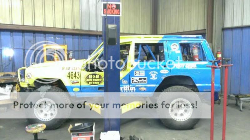
- Location
- Port Orchard, WA
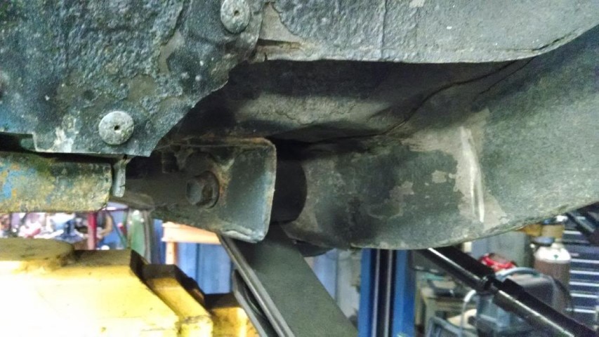
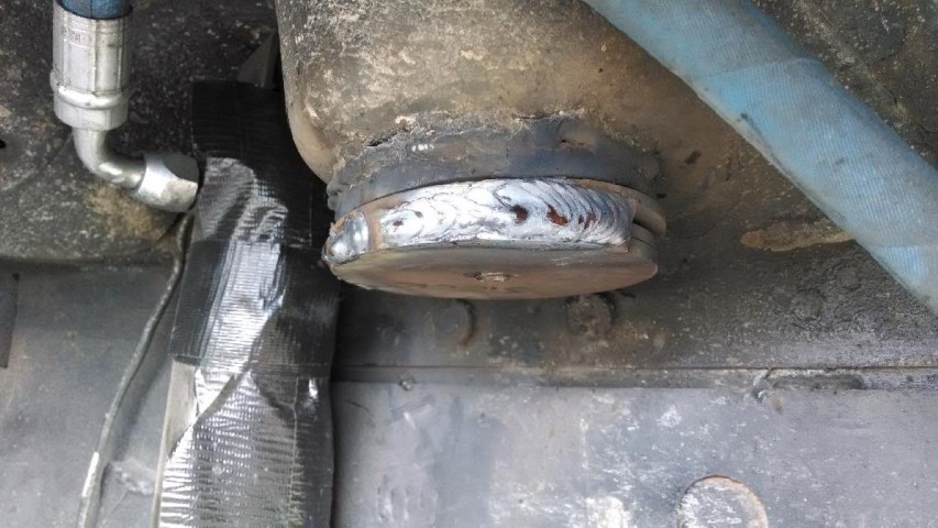
Hard to believe this tie rod has only one race on it. 1.5x.250" DOM..
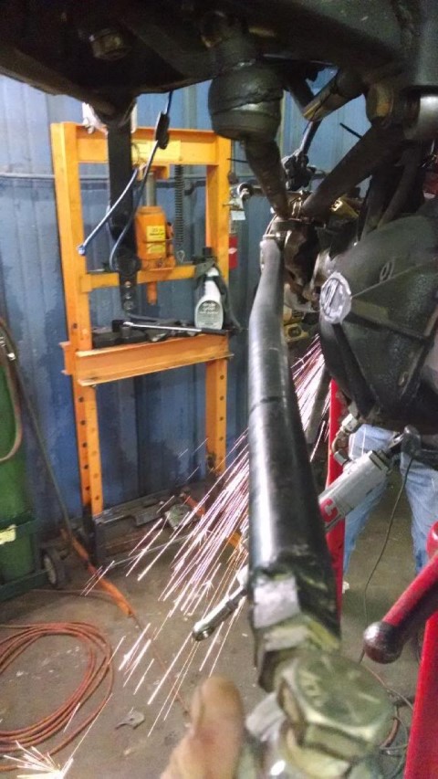
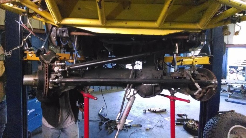
Given the lack of rock rash, and the location of the ram clamp being coincident with the bend area, I'd say that the ram bent it.
Might check the shims in the ram to make sure they're still there.
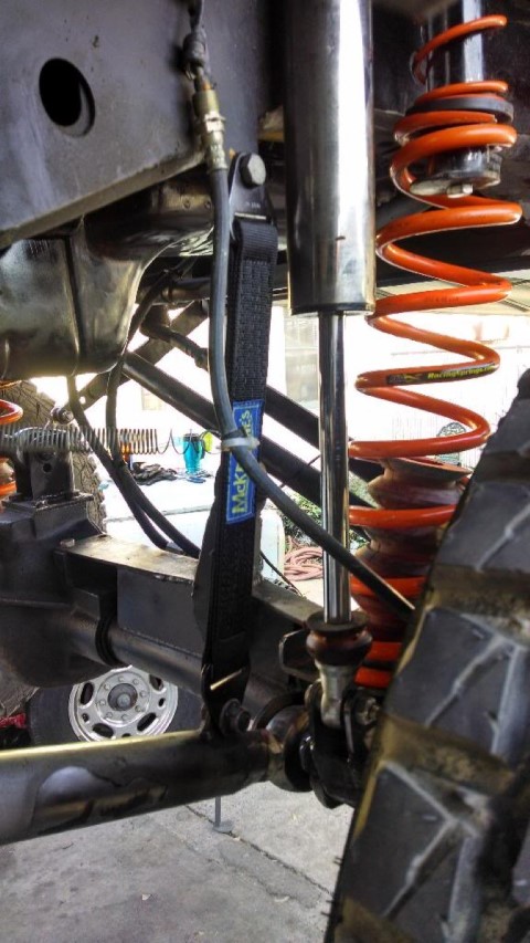
I'm sure you would have if there was room, but I prefer to have the ram bolted to the axle and the knuckle and avoid the tie rod / ram connection if possible.
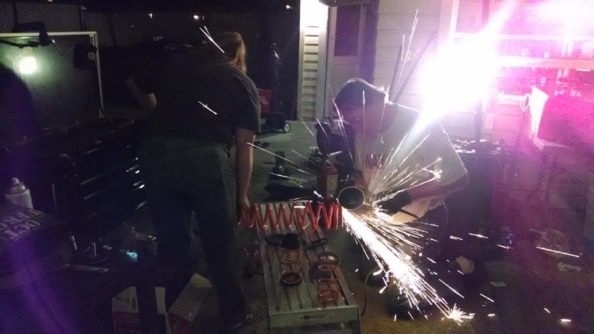
Looks like you guys are having a good time. Keep up the good work.
Last edited by a moderator:

")