• Welcome to the new NAXJA Forum! If your password does not work, please use "Forgot your password?" link on the log-in page. Please feel free to reach out to [email protected] if we can provide any assistance.

Blower Motor Resistor Red Hot?

TheSloMoShow

NAXJA Forum User
Location
Columbus,OH
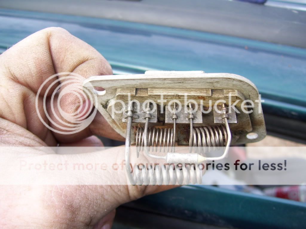
So I replaced my blower motor today, old one was shot (cage broke, bearing ringing). Shortly after replacing it, I found that only the highest speed setting worked. So, pulled the BMR and replaced with a new one.

I tested it before installing back into the dash, and on the two lowest settings, the resistor coil gets red hot. It starts to smell too.
I know there is some special coating on the resistor coils that burns off primarily, but damn, are these really supposed to get red hot??

I've seen some people comment that it's meant to get hot, and that so long as it's placed in the path of the blower motor's air path all is OK.
But I'm having a hard time believing this.

If it's not meant to get red hot, then I'm at a stand still...
 
I'm wondering if it's shorting out somewhere or an improper ground causing it to act haywire?
I wouldn't think so, I just replaced the blower motor with a Four Seasons version. My thought was maybe the new fan was drawing too much current, but I can't imagine how as its brand new.

I've installed it back in its place so the airflow can pass over it, just hope nothing burns up.
 
If the coils are not in the airflow they will get red hot to the point of melting.

The thermal fuse will melt before this happens, opening the entire resistor stack.

Pic of a resistor block showing thermal fuse (tube-like device). It internally melts at around 262*F.

ResistorBlockThermalFuse128C2624FFuse-1.jpg
 
I disagree. The fine wire coil will melt before the fuse when the pack is not in airflow. Had a junior tech in my shop do just that.
 
Does it matter? Operating the blower with the resistor pack outside the airflow will cause a failure, no matter if its the thermal fuse or a coil. Either way, it is out of pocket loss.
 
Yes, but is the norm?
This has become a thought worm in my head and won't go away until I answer.

It is the norm. The coil(s) will burn out first, every time.

The fuse is triggered by a too-heavy load on the circuit, i.e. the current draw from a worn-out motor.

The coil is a resistor designed to be cooled by airflow, right?

The coil getting red hot and eventually melting does not increase the load of the circuit. In fact, it decreases the current draw across the fuse because as the coil gets hot, it's resistance goes up, to the point of failure, to which then, is infinite.
 
The wire in those coils is nichrome and is made to have high resistance. The higher the resistance the slower the motor will turn. Yes it is completely normal for these to get red hot if not in the airflow. This is the same type wire used to make heating elements for electric heaters or the heating coils on your stove.

In a vehicle heater, there will be multiple coils, one for each speed, and each will have a different resistance. While the resistance changes from cold to hot to a point, that is not used in this application.
 
Thanks for the input guys. I had a weird feeling about it, but wth. I guess I'll give the blower a whirl tomorrow. Just hope it doesn't burn out again.
 
If the resistor is fine, and you still burn it out, then you have a problem with the motor pulling too much current.

By the way, that is not uncommon. Over time, the shellac insulation between the wires breaks down and you have a winding to winding short within the armature, which causes excess current draw.
 
TheSloMoShow,

Just FYI:

Here's a schematic of your blower circuit. Note the location of the thermal fuse in the resistor block, and that the '97-'01 controls the blower ground circuit, not its power circuit.

%20Blower%20Rev%201.jpg


Here's a schematic of a '94 blower circuit (typical for '88-'96). Note the switch-like symbol in the resistor block - that's the thermal fuse. Note also that the control system for the blower controls the power to the blower, not the ground circuit. The resistor block carries the full current draw of the motor.

94%20Blower%20Circuit.jpg
Thanks Sidewinder CC. Luckily I haven't had any issues since throwing the new BMR in. But I'm not seeing how in the 97+ that the resistor block isn't also carrying the full current draw of the blower motor as well?
 
Thanks Sidewinder CC. Luckily I haven't had any issues since throwing the new BMR in. But I'm not seeing how in the 97+ that the resistor block isn't also carrying the full current draw of the blower motor as well?

It is. It doesn't matter if the block is in the ground path or the supply path. It still sees the same amount of current. So I'm not really sure where he was going with that, other than pointing out the differences.

What does change is a switched ground doesn't arc as much as a switched supply. So I assume they were trying to reduce arcing and load surge on the switch by changing how the circuit functions.
 
What does change is a switched ground doesn't arc as much as a switched supply.

Where did you get that idea? I'm and electrical engineer with 40+ years experience and can assure you there is absolutely no difference in the amount of spark that can be generated.
 
Pretty sure it was one of the GM training classes I took a very long time ago. I was taught that a circuit controlled on the ground side had less arc potential and thus less transfer of material between the switch contacts, lengthening the service life of relays and the like. Also, connecting the battery ground last causes less arcing as the terminals are connected reducing the possibility of fire.
 
Which, I remember, the part about the battery was directly contradicted by my electronics instructor in A&P school where they taught you to connect positive last as the potential in a battery travels from neg to positive.
 
Back
Top