• Welcome to the new NAXJA Forum! If your password does not work, please use "Forgot your password?" link on the log-in page. Please feel free to reach out to [email protected] if we can provide any assistance.

Anak’s Painstakingly Detailed Armor & Tail Lights Write-up (Dialup Beware)

Anak

Stranger
NAXJA Member
Preamble: This is going to be a long post with a whole bunch of pictures. One reason for the level of detail is so that anyone who would like a set of these can evaluate the option for themselves. This took me about seven months from receipt of armor to final installation. I am not a professional with a bunch of specialized tools. If you can weld then you can probably do this. Note that I am also including my mistakes so that hopefully someone else can learn from them. At the very least it will help me remember not to make them again. I hope.

A big part of the purpose of this thread is to help with reasonable expectations, not to bash anyone’s product. You will note I had some challenges fitting these. I suspect everyone who tries to fit armor on an XJ runs into some challenges. Among other things, the XJ platform covered a span of 18 years and two manufacturers. Neither of those manufacturers have been particularly noted for their ability to maintain world class quality control. I have been involved in manufacturing aftermarket products and I know that dealing with someone else’s tolerances and seemingly random design variations is no small challenge. I am simply grateful for the aftermarket support which I enjoy as an owner of an XJ. It sure beats having to fabricate components from scratch.

I know I am not the only person to purchase something like this and then wind up putting it in a corner of the garage and glaring at it for a few months. I am hoping that by providing the details of my walk through this project I will help others be prepared to deal with the challenges so they can keep moving forward to the end and get there more quickly than I did.

Now, on to the write-up.

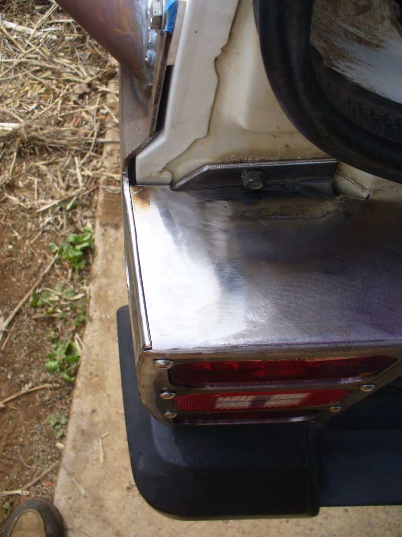
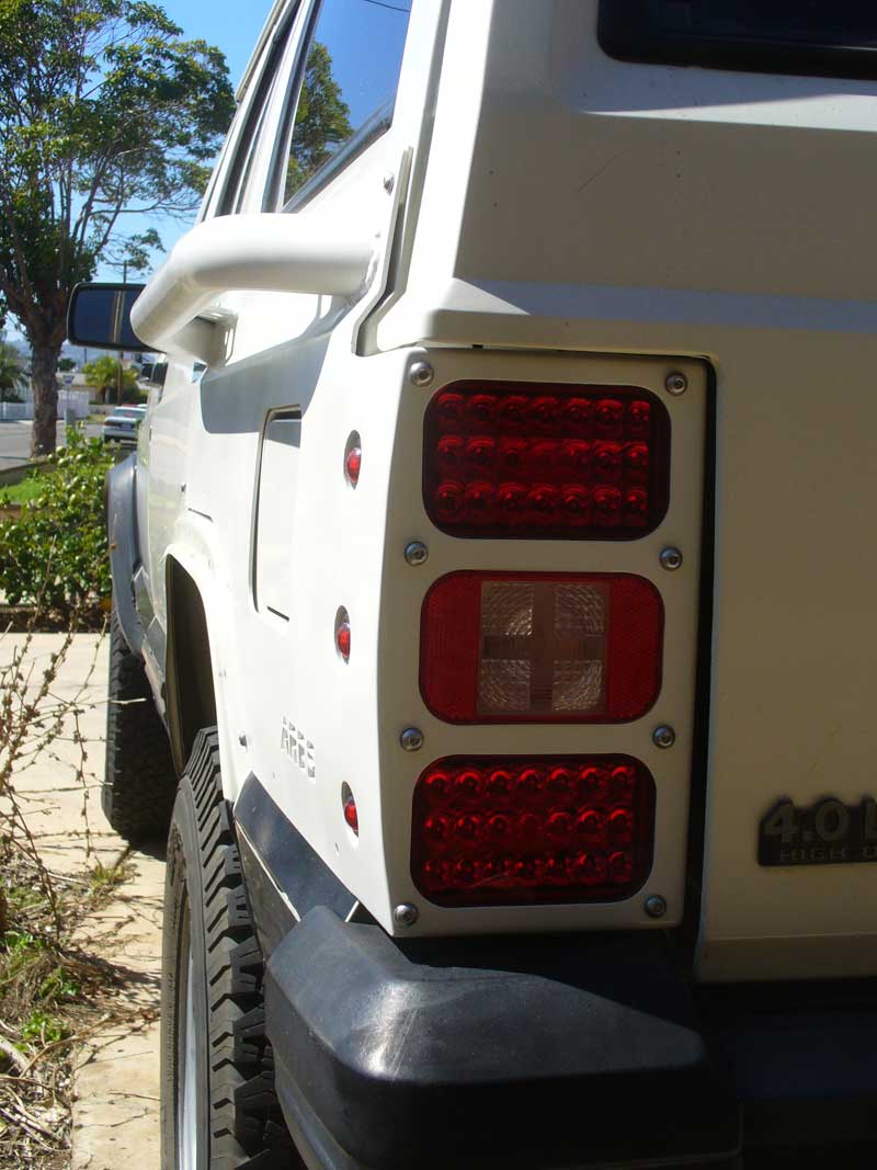
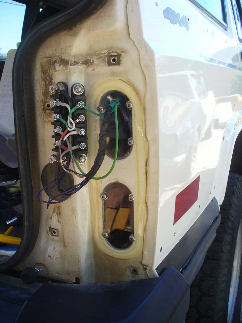
This project got bumped up in the priority list when I found out just how bad the reverse lights are on my ’96 XJ. The first winter of owning my Jeep I didn’t drive it in the evening because the headlights would randomly go out as if this were a British car with Lucas components. Some relays and bits from Daniel Stearn took care of that. But the next winter I found out that the reverse lights are completely useless when it comes to illuminating the area behind you. Perhaps they will alert an attentive driver to your intentions of backing up…perhaps…but they are a sad excuse for a light.

[FONT=&quot]Now that I have gone down this route I think I would have been wise to look into the Oldsmobile Aurora mod, but that tends to preclude the use of a bumper mounted spare tire, and I am not yet ready to give up that option. And I understand that mod requires cutting some holes in the fiberglass hatch. Besides, I like the idea of custom tail lights. I really became committed to the idea when I saw this thread:

http://www.naxja.org/forum/showthread.php?t=1110092

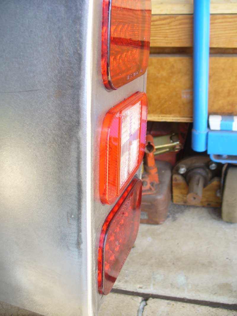
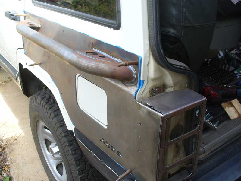
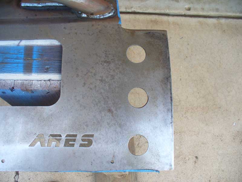
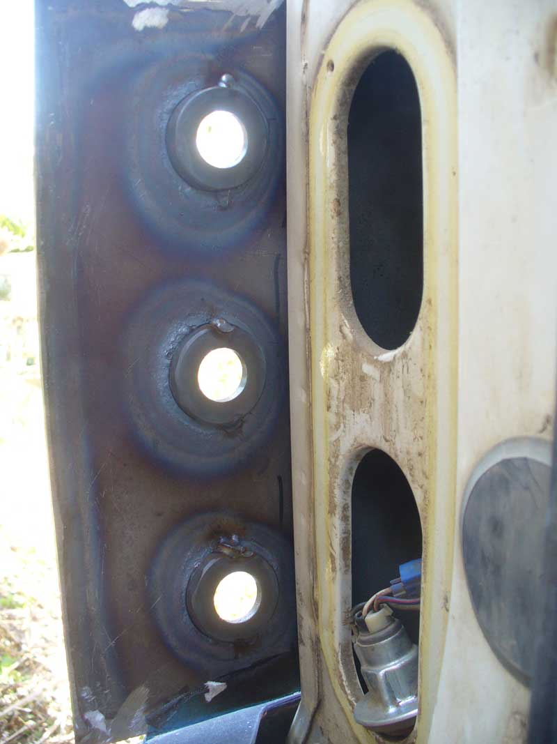
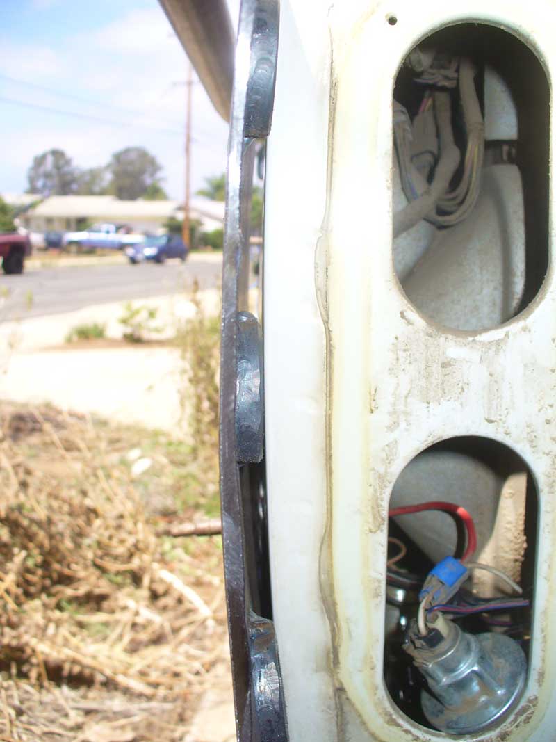
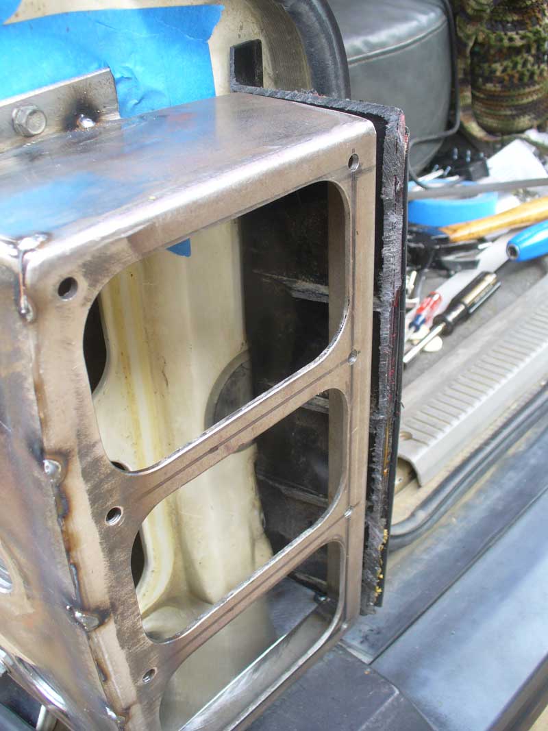
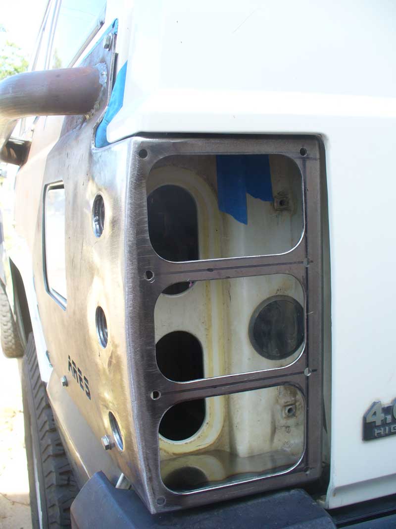
[/FONT] Then it became a question of how to come up with the housings. I could follow the path of the OP in that thread and make my own metal housings, but then I considered the potential risk of something hitting the tail lights and rather than just busting up the tail lights instead transferring the damage to the quarter panels. Quarter panel armor seemed like a good idea, but how to go about getting the rectangular LEDs? Everything I had seen on the market was set up for a pair of 4” round LEDs. I really did not want to try to fill in the existing holes and start all over, but that was looking like my best option.
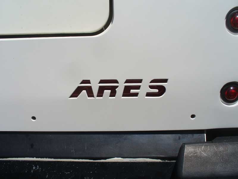

[FONT=&quot]Then I found that Ares Fabrication offer the option of armor with blank light boxes. That was exactly what I needed.


http://aresfabrication.com/?page_id=662


[/FONT] (Note they also make armor for two door XJs. I have seen a number of threads where folks were lamenting the lack of armor for two doors.)


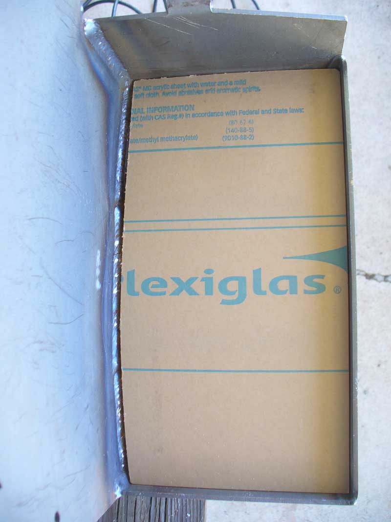
I ordered them in early January and received them in early February. These were a custom order. I expected to wait a bit for them. I still got antsy about getting them, but the time was not unreasonable.


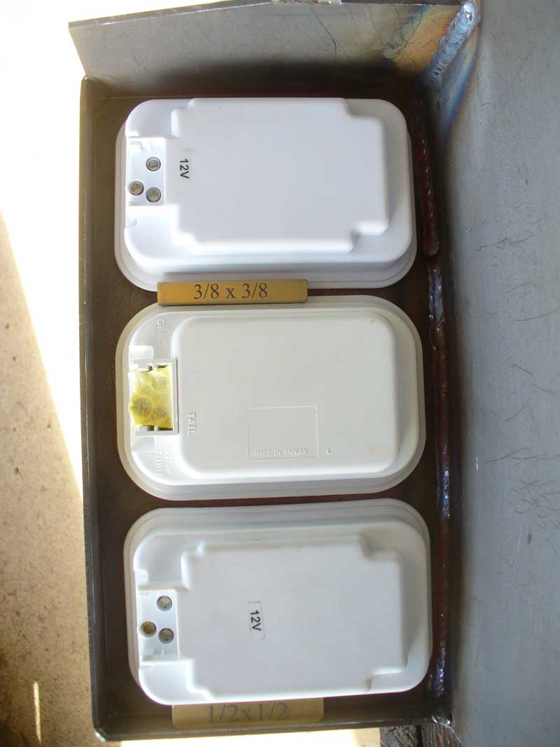
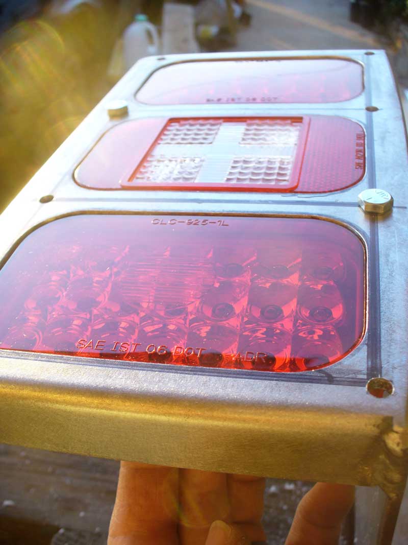
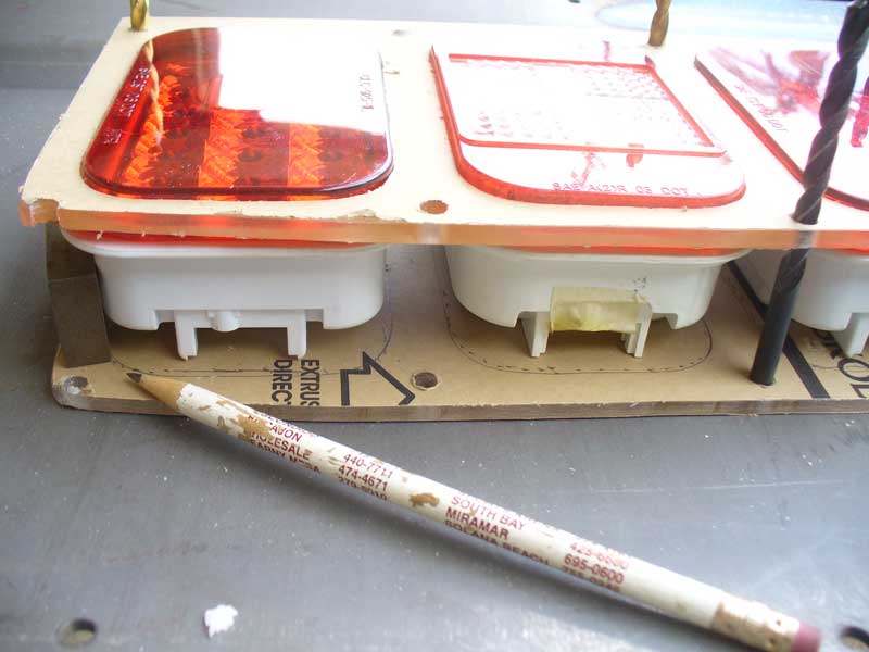
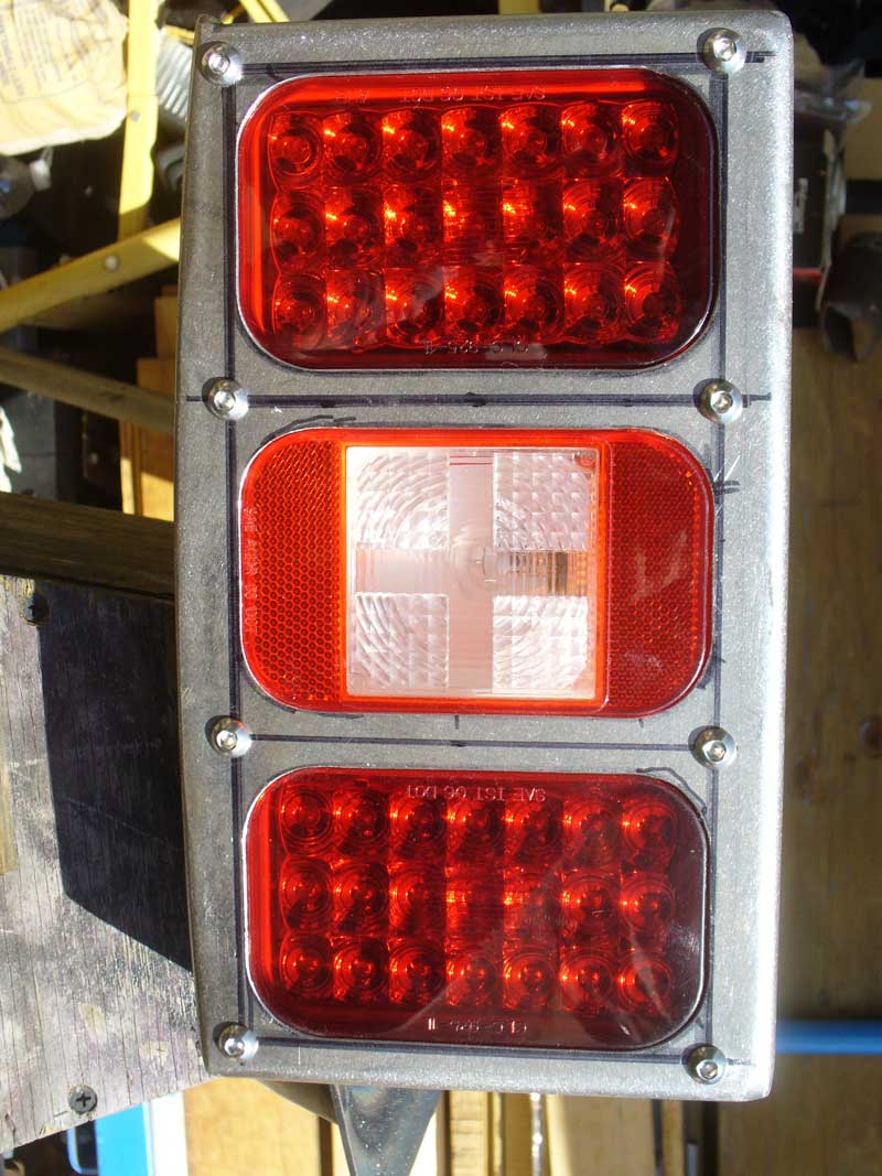
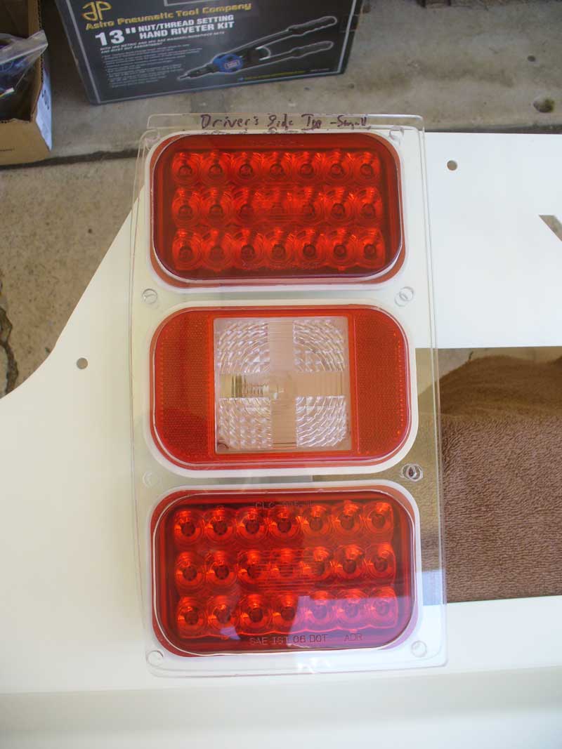
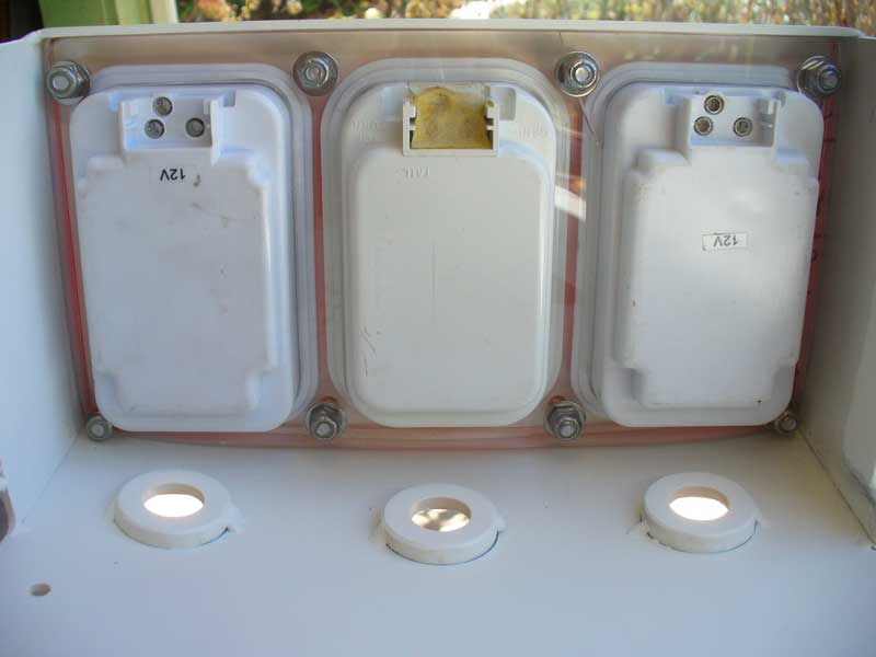
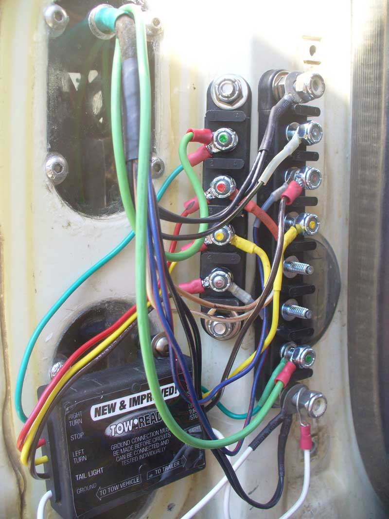
Once I got them and some rectangular LEDs I set to work laying things out. Guess what? Rectangular LEDs are all over the map when it comes to dimensions. I am sure there is some limit on tolerances, but those big rubber grommets seem to forgive a lot of variance. I knew what I wanted to run for reverse lights, but finding a brake/tail light to match was a roll of the dice. My first choice was a no-go. Fortunately the second set I tried was pretty close.


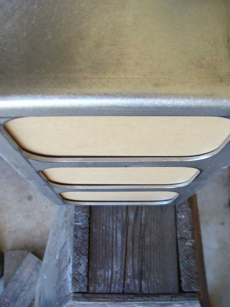
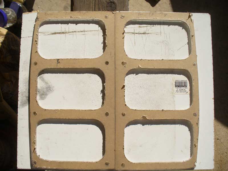
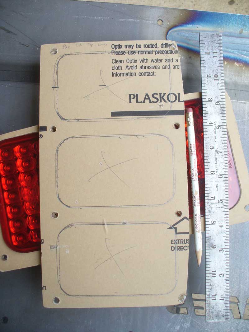
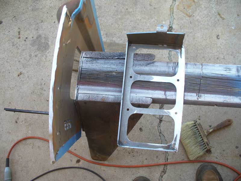
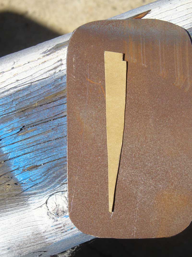
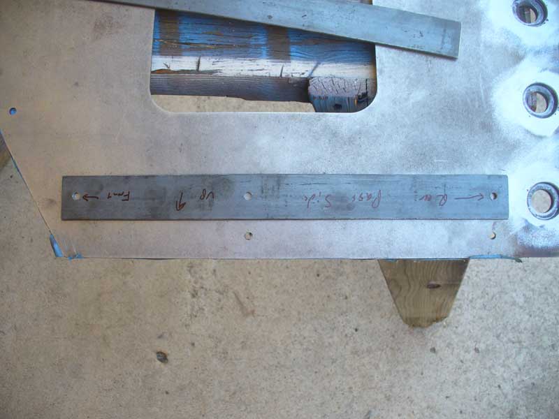
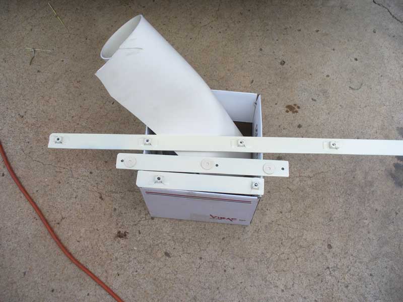
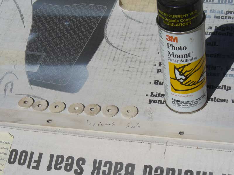
I set to work laying things out with my sophisticated CAD system.


XJTaillightsDay1OPT6.jpg


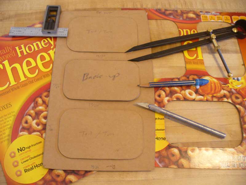
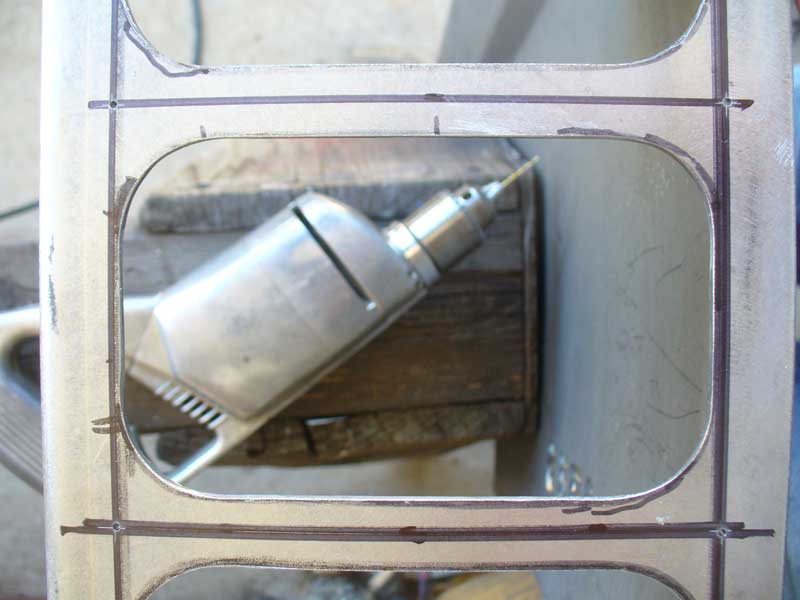
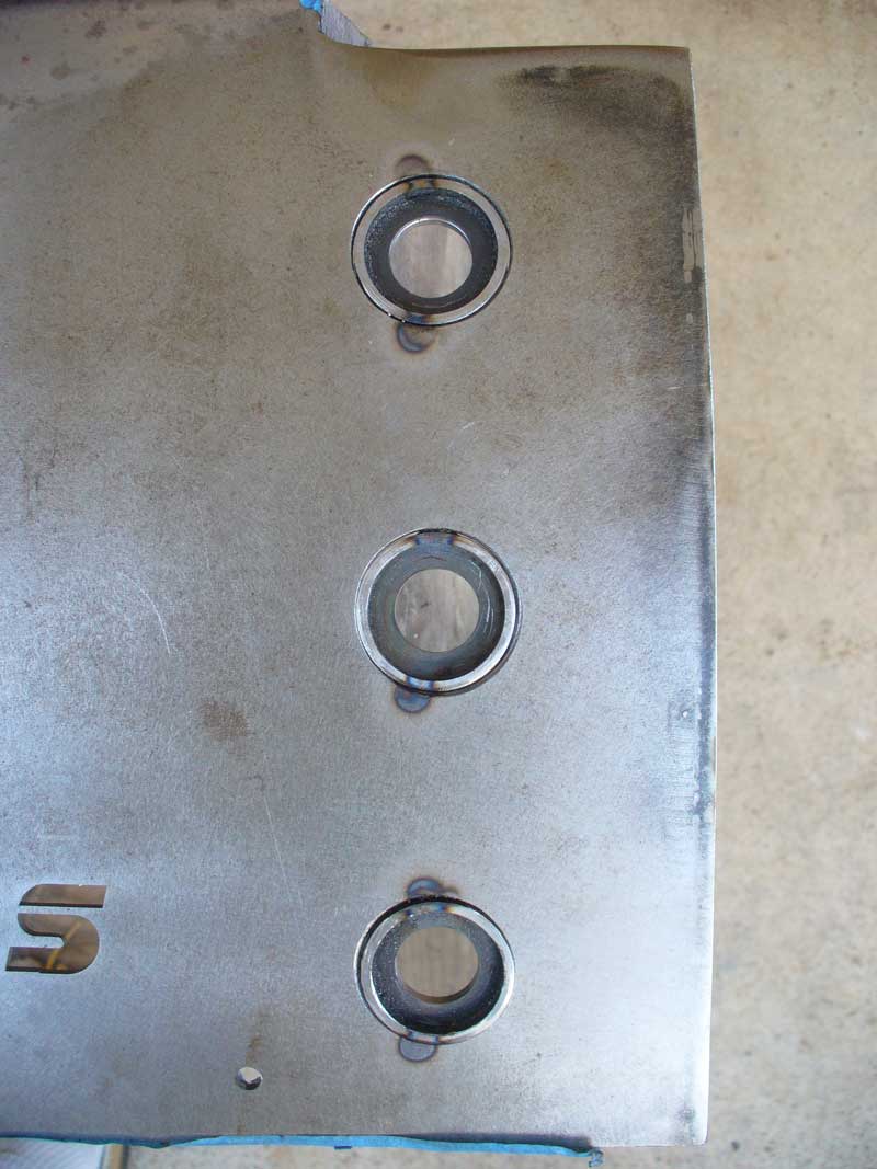
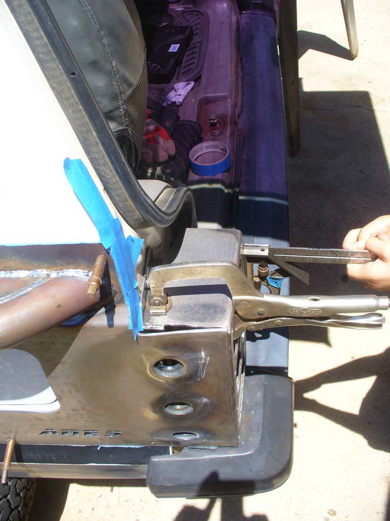
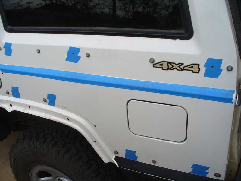
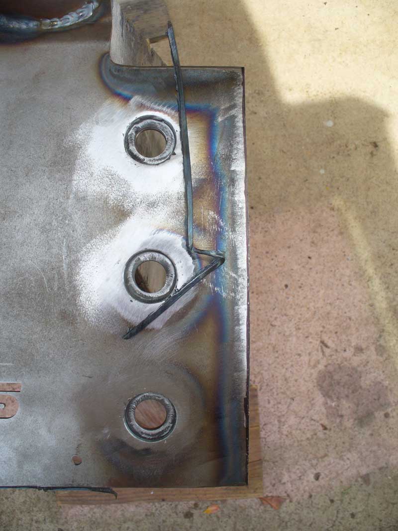
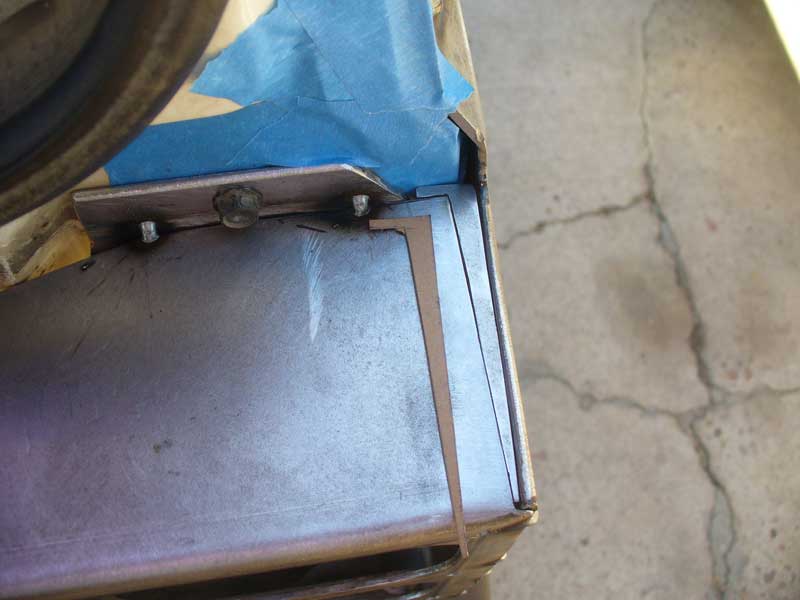
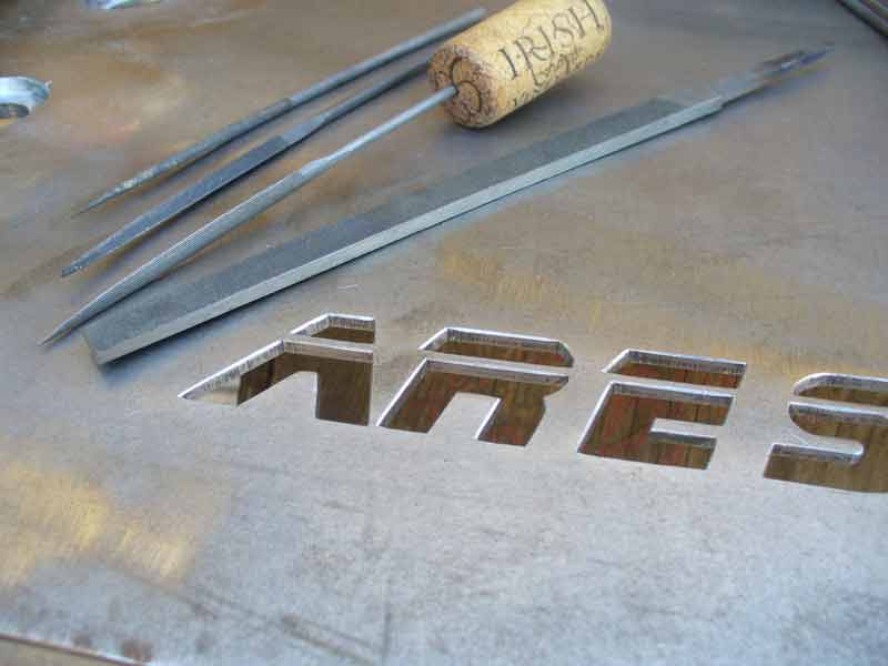
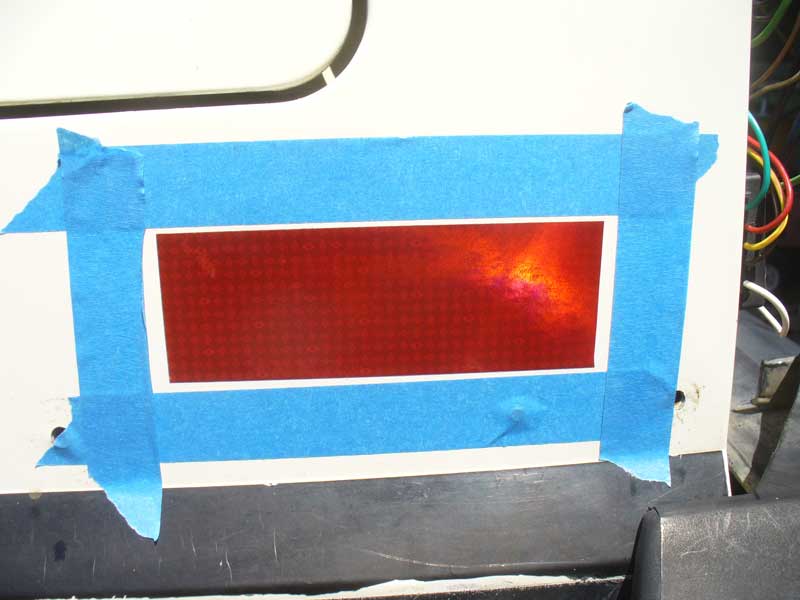
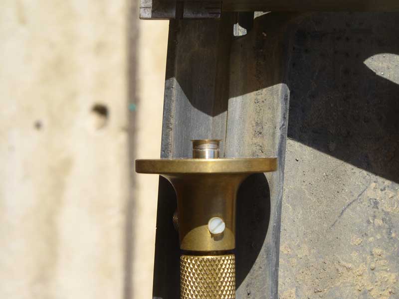
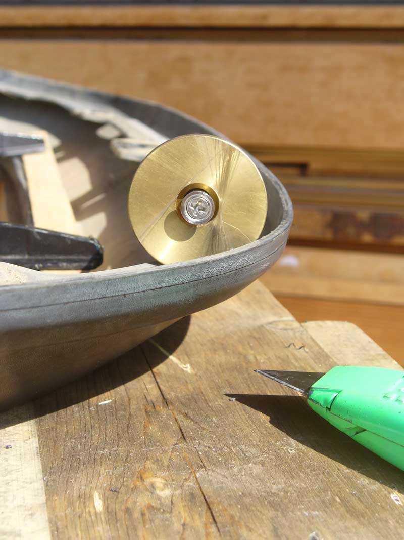
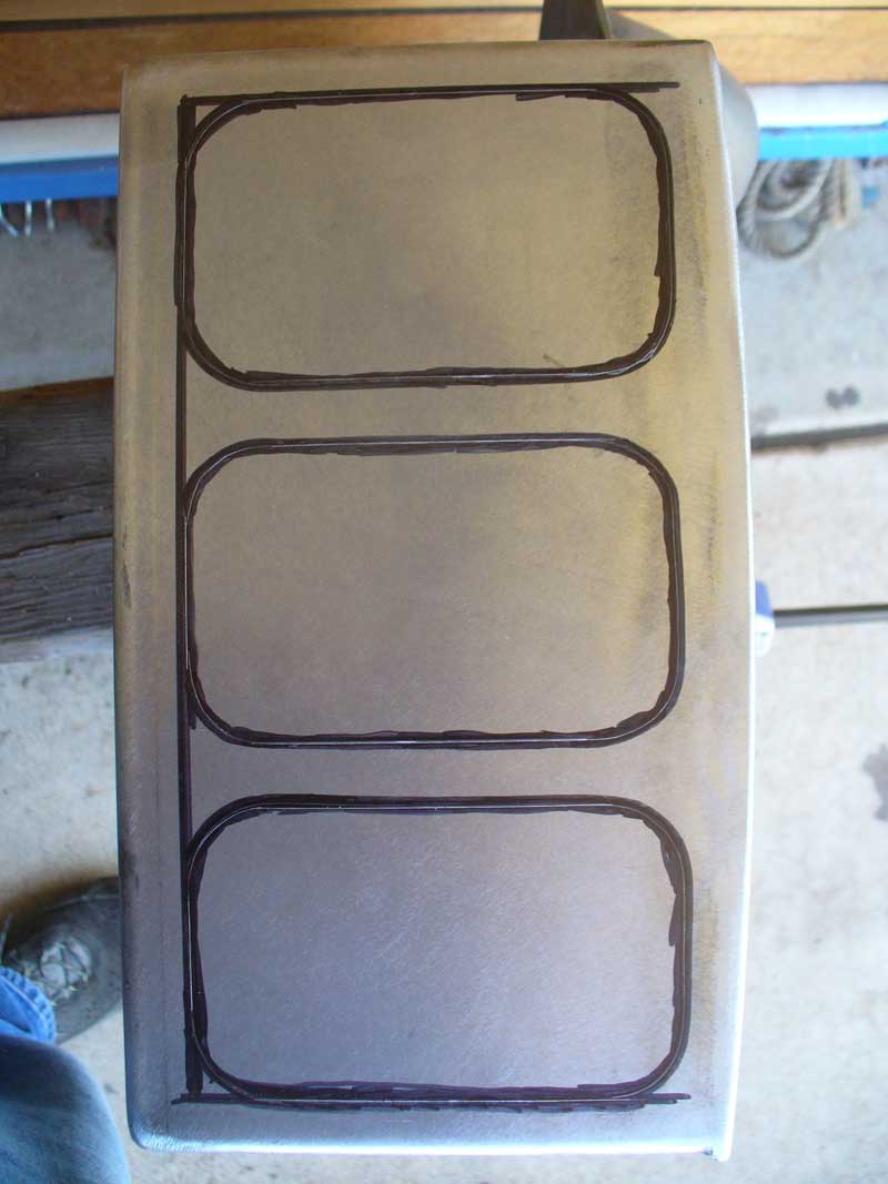
I then transferred my patterns onto the blank tail light boxes. I first traced with a Sharpie, then widened the Sharpie tracing, then again traced, but this time with a scribe tool. That gave me a nice fine line with good contrast.


XJTaillightsDay1OPT7.jpg


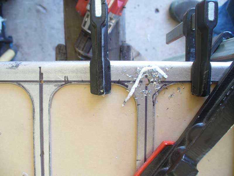
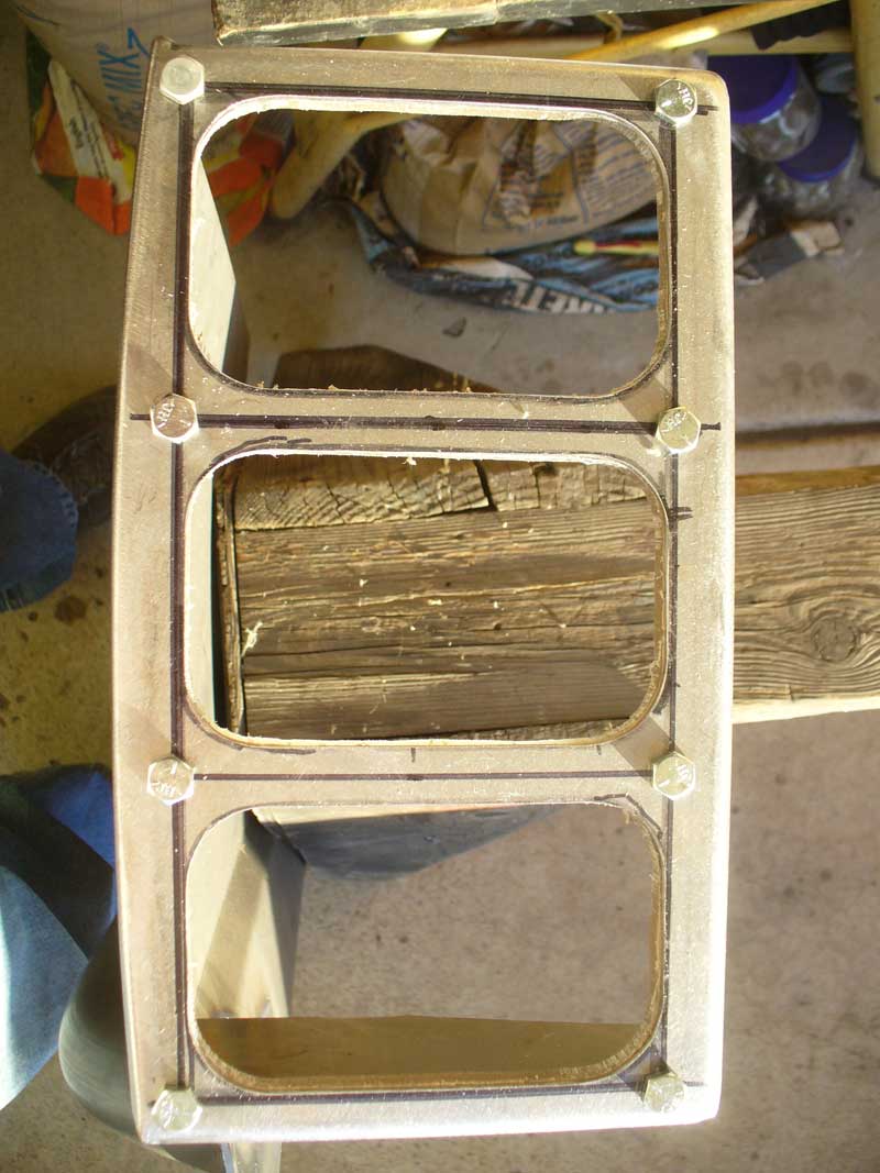
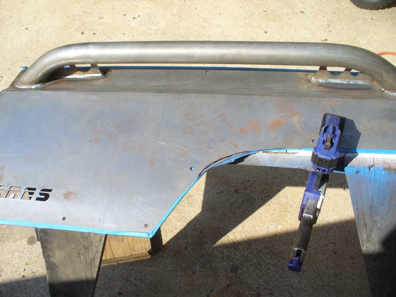
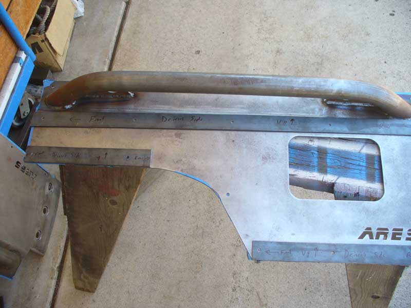
I clamped both pieces of armor to a sawhorse.


XJTaillightsDay1OPT15.jpg


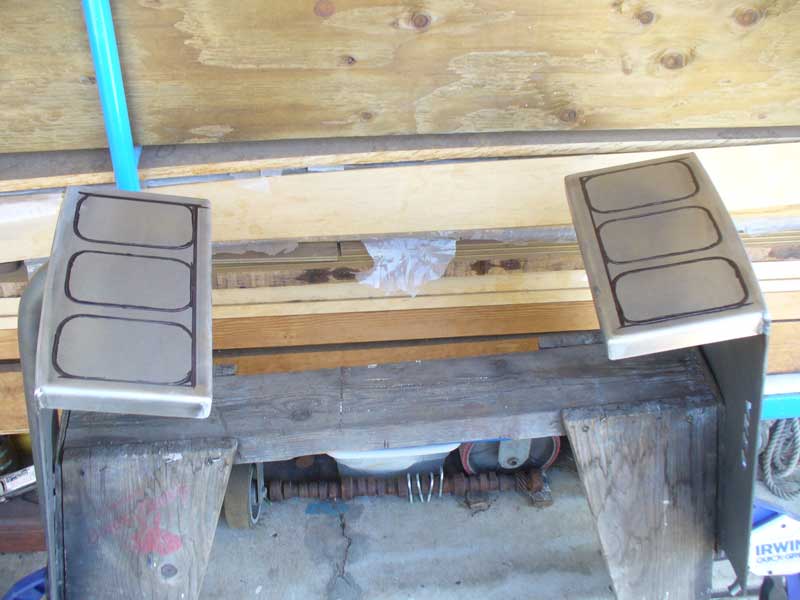
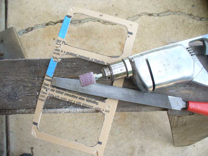
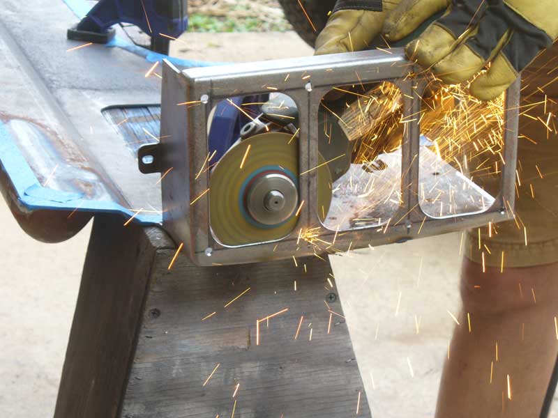
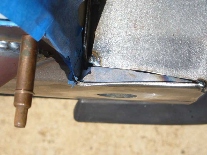
I then used a 4 ½” angle grinder with a cut-off wheel to plunge cut along the inside edges of the straight lines.


XJTaillightsDay1OPT19.jpg


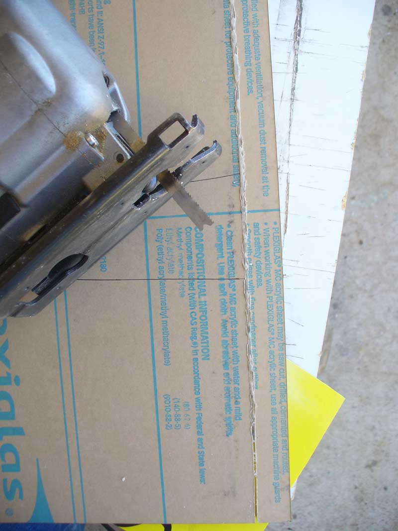
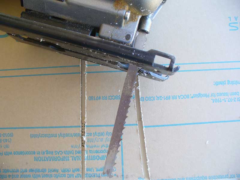
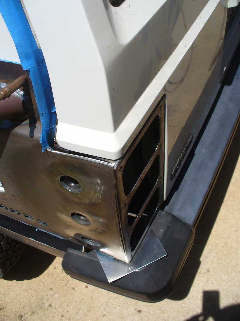
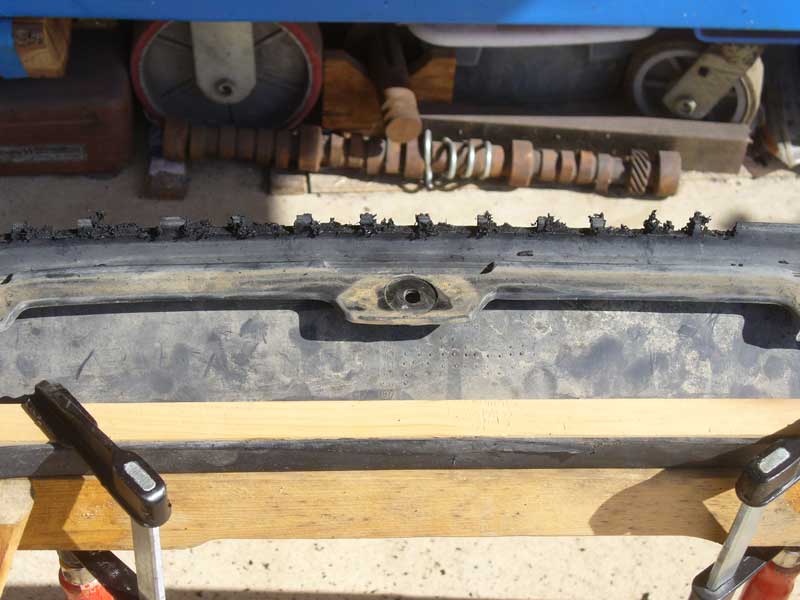
I then used a jigsaw with a metal cutting blade and lots of wax from a nixxstick in order to make the curved cuts. I left just the smallest bit of material at each corner for the sake of stability until I had made my way around the fourth corner on each opening.


XJTaillightsDay1OPT22.jpg


Then it was just a matter of removing the little tabs to drop out the center.


XJTaillightsDay1OPT24.jpg


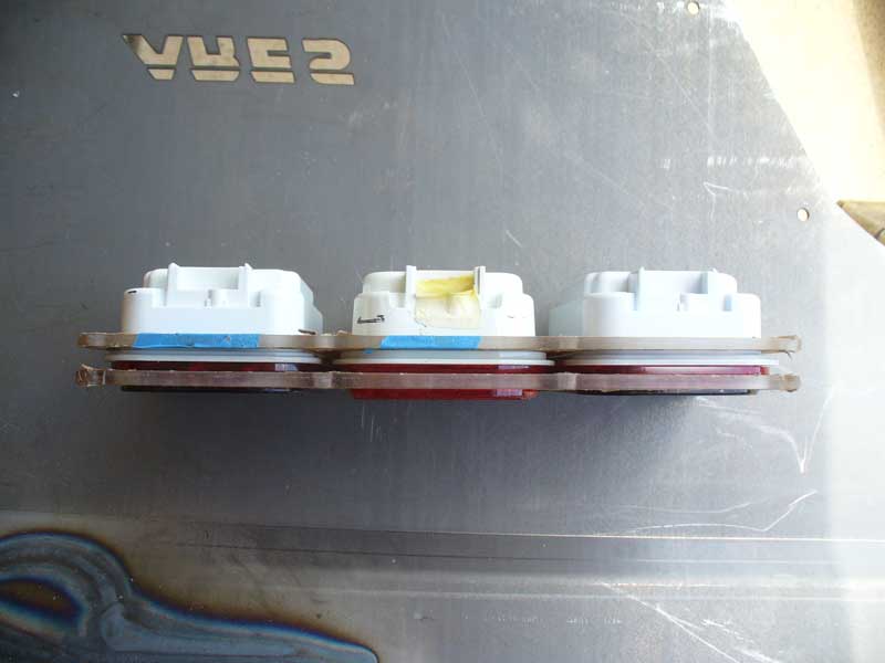
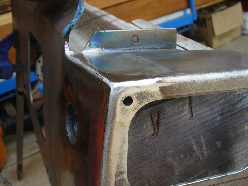
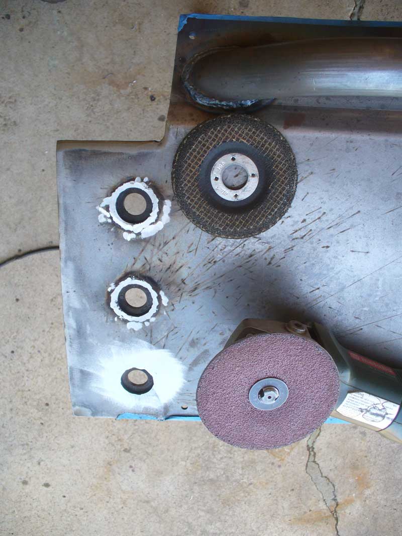
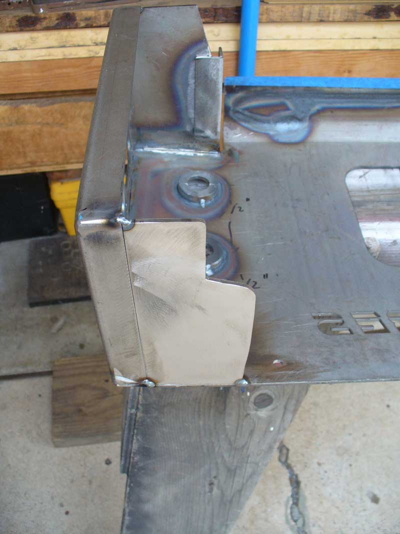
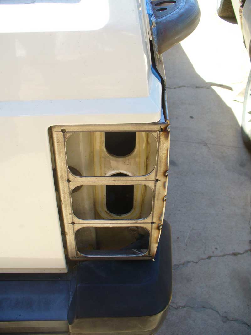
By the late afternoon I had this:
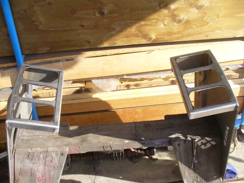
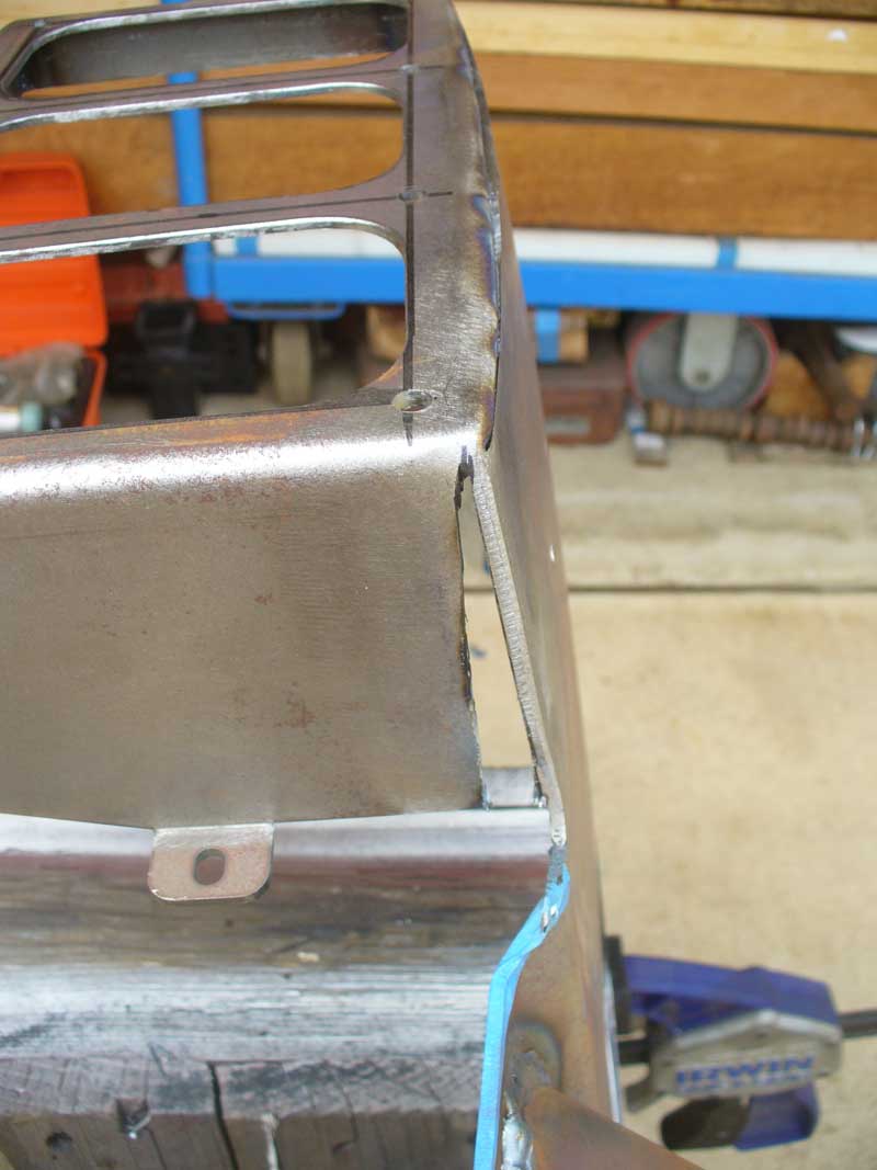
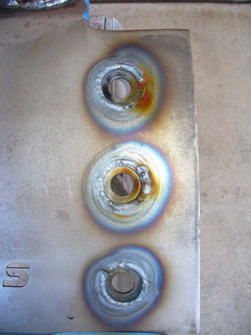
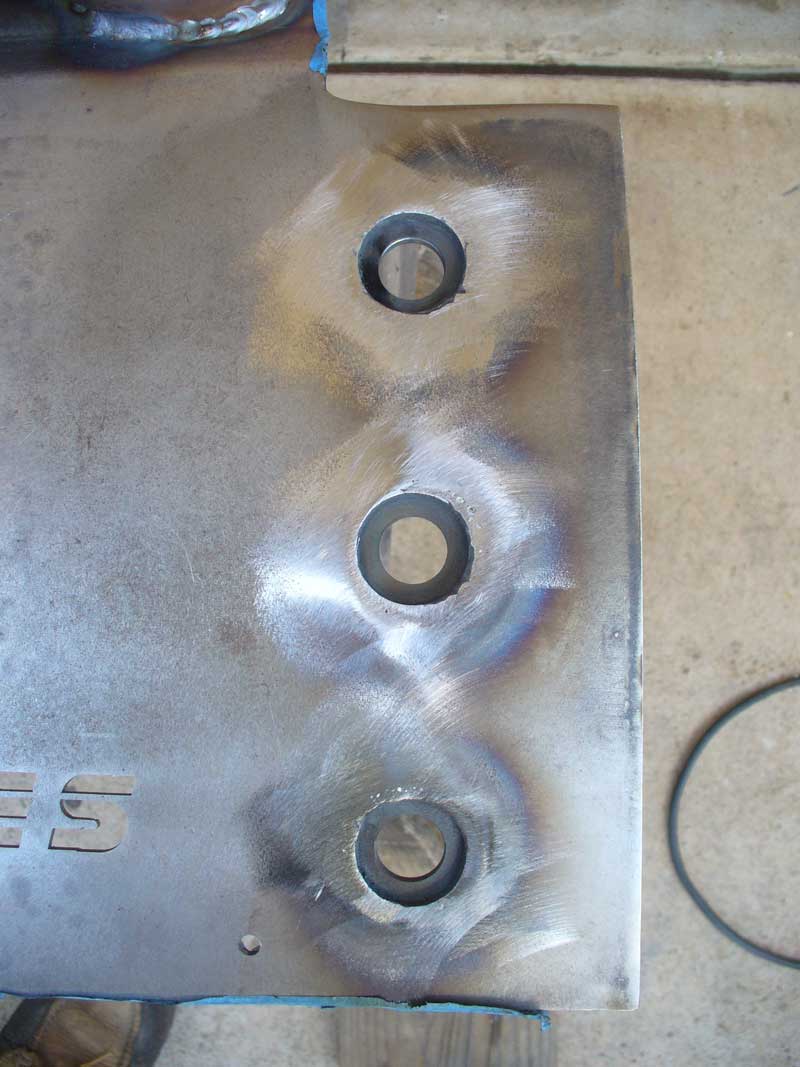
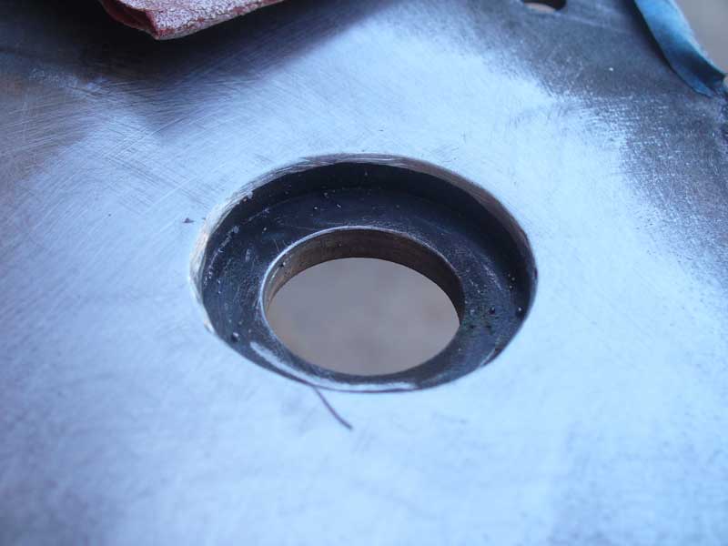
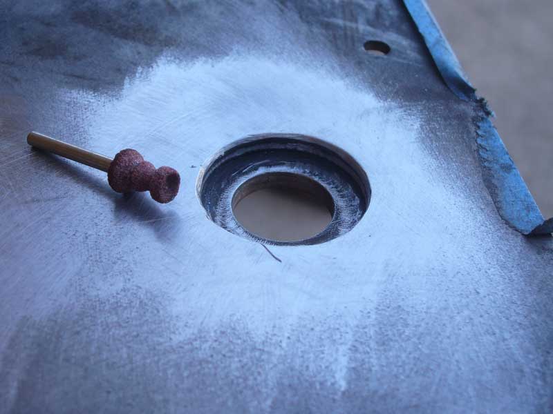
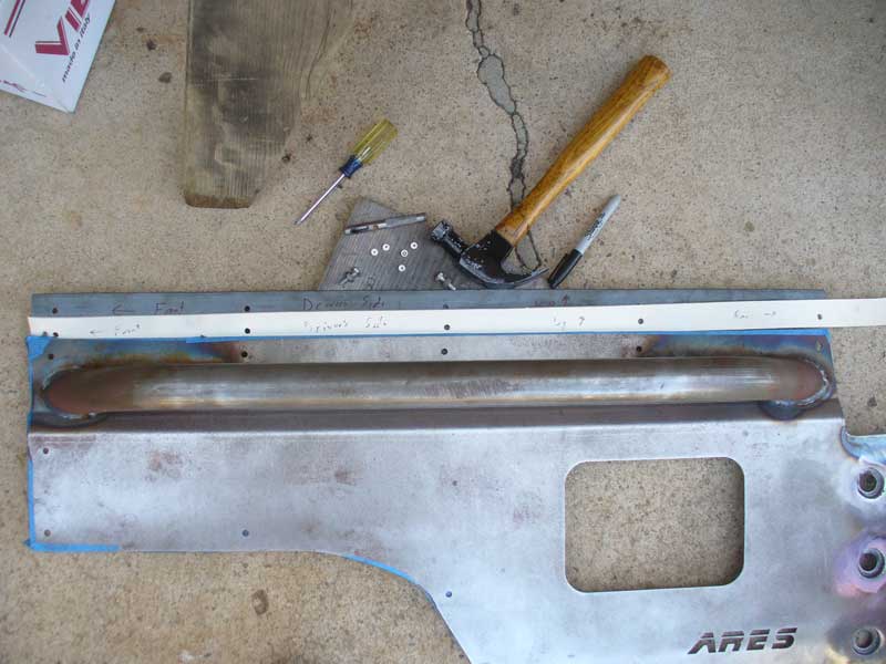
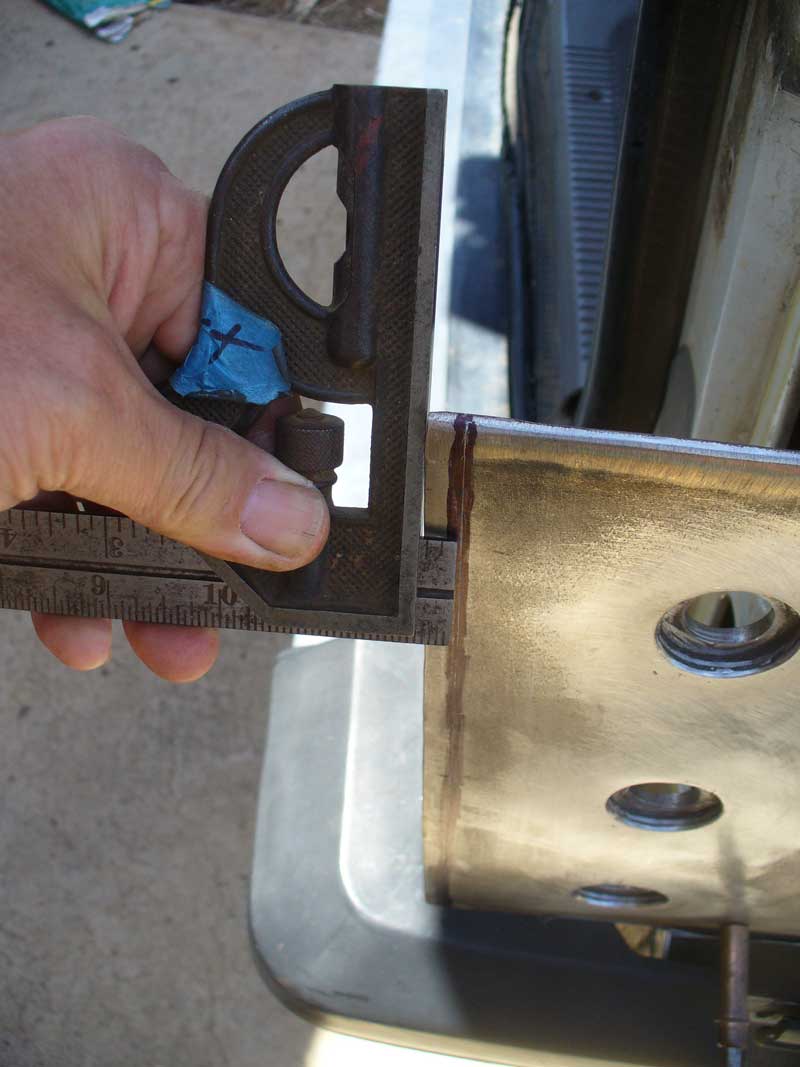
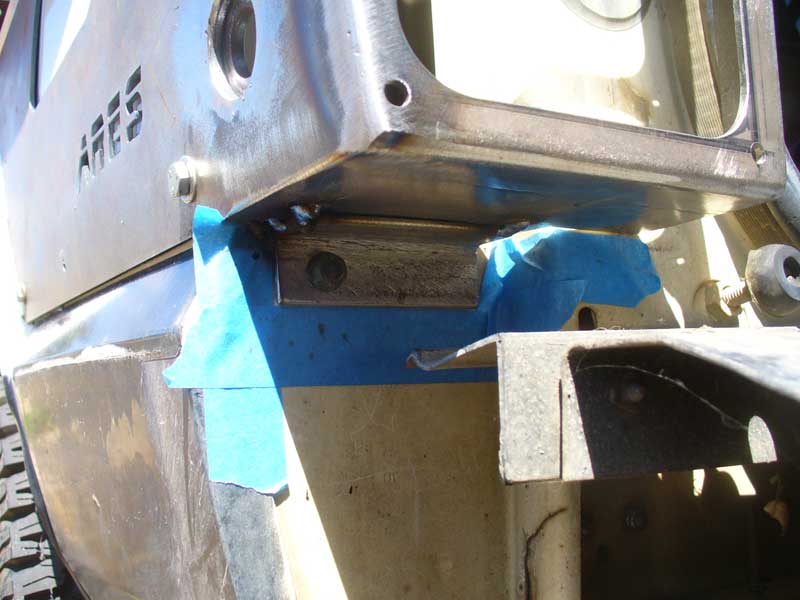
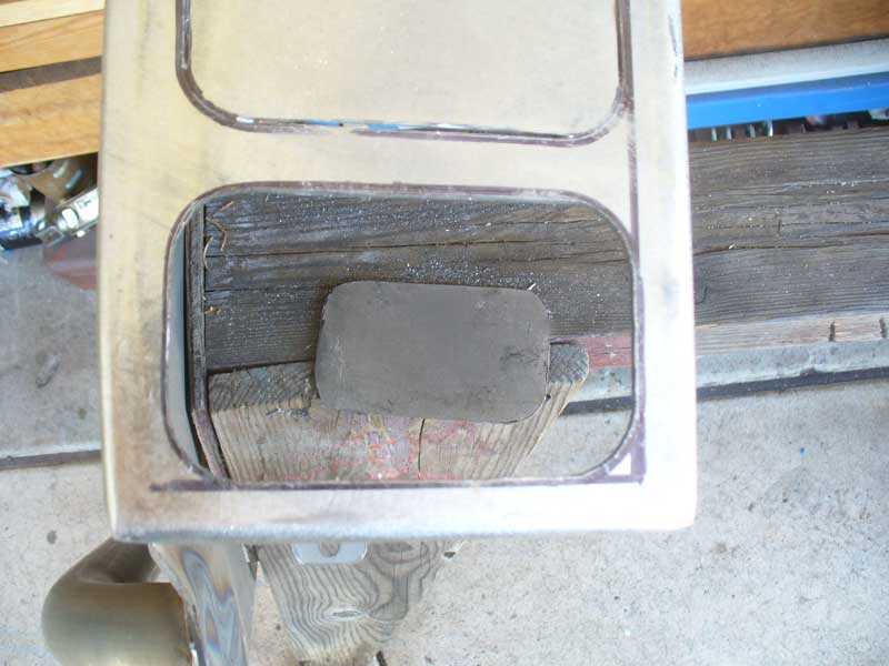

XJTaillightsDay1OPT27.jpg


[FONT=&quot]From there it was a whole lot of grinding and filing to sneak up on the final dimensions. I probably spent about two hours per opening. The entire time I was thinking how much easier this would be if done on a plasma CNC. The closer you can cut to your final line without going beyond it the less effort required to achieve a final fit.[/FONT]
 
Here we are getting somewhere:


XJTaillightsFitment1.jpg


And here we have all three lights on one side:


XJTaillightsFitment2.jpg


As you can see, they stick out a bit though. I knew they would. I need to make a spacer to recess them back by about 3/16”:


XJTaillightsFitment3.jpg


And here is a shot giving a sense of what I have for spacing on the inside:


XJTaillightsFitment4.jpg


So the next step is making spacers. It used to be called Ridout Plastics. Now it seems to be E-Plastics, but I have a place near me that sells remnants by the pound. A couple of dollars got me some plexiglass to play with. I figured that was my best bet in materials. Fairly light weight and not likely to expand when wet. Easy to work with. Probably all the strength I need for this application. Aluminum would pose a problem with electrolysis and it gums up a file.


Plexiglass cuts fairly easily, but if you are using a reciprocating saw make sure you choose a blade with plenty of set to the teeth. These nicely ground teeth that leave a beautiful finish on wood just don’t create a wide enough kerf. The plastic melts back together behind the blade. It is a bit of a surprise when you cut all the way through just to find that your pieces are still attached to each other…You can see that I made a cut that was good for about an inch. From that point on it just melded back together.


XJTaillightsFitment5.jpg


I switched to a more aggressive blade and things went much better.


XJTaillightsFitment6.jpg


The plexiglass was cut to fit in the tail light box.


XJTaillightsFitment7.jpg


Funny, it doesn’t sit quite flush. Note the shadows. That was courtesy of weld spatter. A bit of effort with a dremel tool to get into the inside corners took care of this.


XJTaillightsFitment8.jpg


Before I could go any further I realized I needed to ensure that the plexiglass stayed put relative to the metal. It was time to commit to my mounting system. I had toyed with welding in threaded inserts on the back side and using screws from inside to retain everything and keep a cleaner look. I realized that was going to be a royal PITA, and besides, the armor already involves a bunch of exposed hardware. I decided to keep it simple and just match the mounting hardware that was already involved.


Time to layout lines and drill for the mounting of the light spacers and retainers.


XJTaillightsFitment9.jpg


With the pilot holes in place in the armor I then clamped the plexiglass in place and drilled both armor and plexiglass to size. I prefer pilot holes in metal, but I have had bad luck with them in plastic. The angle on the drill bit seems prone to splitting the plastic.


XJTaillightsFitment10.jpg


Locating off the bolt holes to keep things stable made it easy to trace the pattern. I mark material to be removed just so I can keep track of what I am doing. Also, which side is up. Saves a lot of confusion later on. Particularly after multiple interruptions from Varmints. Note the value of the paper on the plexiglass. Leave it there as long as absolutely possible. It protects the plastic and adds a form of strength to it as well.


XJTaillightsFitment11.jpg


With the pattern marked holes are drilled for the inside cuts with the jigsaw and then the inside cuts are made.


XJTaillightsFitment12.jpg


Here are the two spacer frames, cut out and waiting to be filed to fit.


XJTaillightsFitment13.jpg


Filing to fit plexiglass is much easier than filing steel. And now I have the metal of the armor to provide a reference surface against which to work. Here is one side bolted up, ready to be filed:


XJTaillightsFitment14.jpg
 
Last edited:
And here is the result once filed down. Pretty close to flush.


XJTaillightsFitment15.jpg


Next up is the retaining frame for the back side of the LEDs. It is pretty close to being the same thing as the front spacer ring, but not quite. It can be a little larger since it does not have to accommodate the weld beads in the corners, and of course the LEDs are not shaped quite the same on the back side.


First step is to cut the blank to fit inside the light box. Then place it in the box, drill for the mounting bolts to locate it securely and then trace the openings.


XJTaillightsFitment16.jpg


Once traced this should be the picture:


XJTaillightsFitment17.jpg


Now the trick is to get an outline of the back side of the LEDs. There is probably a way to measure all this and take the guesswork out, but I could not come up with a method that looked workable with the tools I have on hand. I simply tried to transfer edges using a block of steel that fit between the plexiglass and the LEDs. All I need are some reference points and then it will just be a game of connect the dots.


XJTaillightsFitment18.jpg


Here they are with the dots connected. You can see how the lines for the back are different from the lines for the front.


XJTaillightsFitment19.jpg


Here is how the retainer fits after cutting with a jigsaw (same process as for the spacer frames).


XJTaillightsFitment20.jpg


Now we are back to grinding and filing.


XJTaillightsFitment21.jpg


Fitted together after filing/grinding:


XJTaillightsFitment22.jpg


And finally mounted in the box, as they will be seen:


XJTaillightsFitment23.jpg


And this is the picture on the inside. One of the nuts is too close to the corner to even put a socket on it, but this will work.


XJTaillightsFitment24.jpg


Next it is time to worry about the side markers. I spent a lot of time trying to figure out what to do for side markers. I really wanted some kind of rectangular LED to keep up with the theme, but I could not find anything that fit the bill. The third brake light on the “new” Beetle looked like it might have potential, but those are not readily available in my local junkyards, and besides, that is intended as a bright light (brake) rather than a tail light. What I did find were some very compact round LEDs. I knew that I would have no problem fitting these. They could practically tuck in between the tail lights.


XJTaillightsFitment25.jpg


With what appeared to be plenty of room to play with I decided that I wanted to try to recess these lights into the panel and try to fit three of them rather than just two. I made some little cups to mount them and decided that this was the sort of arrangement I wanted:


XJTaillightsFitment26.jpg


Now we are starting to get close to the body. At this point I need to stop and check and see whether or not this arrangement will indeed clear the quarter panel.


And here is where the fun begins…


I had not yet done a test fit on these panels. Doing so requires removing the tail lights and the fender flares and doing something to protect the finish on the vehicle. That is tedious stuff, and not nearly as much fun as fitting the LEDs in these boxes. So I put that off. Bad on me. Although I am not sure it would have made much of a difference in the end. But here is what I found:


XJTaillightsFitment27.jpg


You may notice a bit of extra rust on the armor at this point. That is because this picture was taken after I actually found this problem. At the point I found this problem I simply put things back together on the Jeep, put the armor in the garage and put the project on the back burner. Let’s just say I was not happy and did not think to take any pictures at the time I first found the problem.


[FONT=&quot]I did not figure there was any point in contacting Ares Fabrication about this. In fact, looking at the pics on their site, and after dealing with what I did in order to get things to clear the hatch it is entirely possible this is the intended design. More or less. The mounting tab for the upper tail light bolt did not line up with the hole, but that was off by an amount that could have been caused by contraction while welding (I re-created that problem for myself further along). The overall angle could be intentional. If you consider the possible complaints from customers who installed your armor and then busted up their hatch the first time they closed it I can see why a manufacturer would go to such lengths to make sure there is no interference. Nonetheless, that angle was not one that I was willing to live with. That was going to have to change.[/FONT]
 
Last edited:
Trying to bend things along a curve was going to be a non-starter. I could not think of any solution less drastic than this:


XJTaillightsFitment28.jpg


Three careful cuts gave me the ability to bend things like this:


XJTaillightsFitment29.jpg


So that it could then mount like this:


XJTaillightsFitment30.jpg


Unfortunately, that did not provide especially good clearance for the hatch. This is not the ideal picture. It does not show how tight the hatch is to the top of the tail light box. What it does show is that I have the armor as low as I can get it on the body line:


XJTaillightsFitment31.jpg


Fine. Cut the box off entirely:


XJTaillightsFitment32.jpg


In earlier pictures it can be seen that there is about an eighth of an inch of side armor extending below the bottom of the tail light box. Plan is to lower the box that eighth of an inch, taking advantage of the material available there. But, now that the box is removed from the side panel it is much more convenient to use the drill press to make the openings for the side marker lights. Time to get to work on those.


Holes drilled with a hole saw (rota-broach would have been nice):


XJTaillightsFitment33.jpg


Tacked:


XJTaillightsFitment34.jpg


Tigged:


XJTaillightsFitment35.jpg


Ground down (did not use enough rod, too many low places…I did the other side with the MIG):


XJTaillightsFitment36.jpg


Clearance to the body:


XJTaillightsFitment37.jpg


Now it is time to put the tail light boxes back on. It is one thing to move something around a bit while it is still partially attached. It is another matter entirely to get it to hold still while not being attached at all. I solved this problem with a piece of 1” angle iron which I drilled for the original, top tail light mounting bolt. I measured for the hole half by calipers and half by eye. Once I bolted that piece to the body I could then clamp the tail light box to it and have a point of stability from which to work.


XJTaillightsFitment38.jpg


Now we are getting to the fit that I wanted:


XJTaillightsFitment39.jpg
 
Last edited:
I made a spacer to fill the gap at the top. How handy that I had some of the original material from which to make it. That bit of patina was just enough in which to scribe a line:


XJTaillightsFitment40.jpg


And here we have it fitted up, ready to weld:


XJTaillightsFitment41.jpg


Welded and ground:


XJTaillightsFitment42.jpg


And guess what? It doesn’t fit. Illegitimate offspring of a female dog.


XJTaillightsFitment43.jpg


XJTaillightsFitment44.jpg


Whisky Tango Foxtrot


I wanted to walk away from this for a few more months, but I also remembered why I bumped this to higher priority. At this point I was getting close to school starting back up (homeschooling, and I am the teacher) and then the time change will come and I will be back to cursing my lack of back up lights. Time to really take a hard look at what I am doing wrong.


First off, the body and the panel are not a perfect match. This is to be expected. There are too many variables between the one manufacturer of the vehicle and the other manufacturer of the armor. I think these two pictures will show the variation lengthwise:


XJTaillightsFitment45.jpg


XJTaillightsFitment46.jpg


That should show that I have a pretty healthy gap at the back of the quarter panel, but I am pretty much right up against the quarter panel in the middle (gas door). The Jeep has more curvature than does the armor. That is allowing for some variation in location. Especially when combined with the Clecos. Clecos are wonderfully useful tools for holding a panel in place, but these are pretty heavy panels, Clecos are not especially strong, and the contraction force of a cooling weld is entirely in another league.


I should have done this at the very beginning, but of course the light boxes interfered and would not allow it, but it was time to really mount these panels. Not a temporary mount, but the way they would be mounted for good. The panels came with nutserts for mounting. I am not particularly crazy about nutserts and wanted to come up with something better. Having spent some time wrestling with these things I decided I wanted nut strips on the inside of the quarter panels. I had never played around with weld nuts before, but I suspected those would be a better choice than just welding bare nuts to a steel strap. I did some hunting around and placed an order for 20 weld nuts so I could play around with them (I should have ordered 24, but I wasn’t entirely sure if they would even be a reasonable option. I now think they are the cats meow.)


While waiting for materials to arrive I spent some time prepping the passenger side panel.


I found that the armor and the body were not fitting together well around the wheel opening. I needed to open up the armor a bit in order to get it to sit flush with the body. I wound up going back and doing this same thing on the driver’s side too. The line from a Sharpie is the material to be removed:


XJTaillightsFitment47.jpg


For the side marker lights I decided to MIG this side. For me it was quicker and involved less heat on the panel (which means less chance of distortion). On the other hand it means more grinding and dealing with spatter on inside corners.


XJTaillightsFitment48.jpg


XJTaillightsFitment49.jpg


A Dremel took care of the spatter inside the side marker cups:


XJTaillightsFitment50.jpg


Then I started making my nut strips. I bought a 10’ stick of 1 ½” x 1/8” HRS. That wound up being perfect for what I did, but I think an even better job could be done, but it would require another 4’ or so of material. All I did was make nut strips for three straight runs of bolts. On each panel that leaves two bolts that are not running through the nut strips. I decided I could live with two nutserts per panel. I was really unsure if a dog-leg nut strip would be a viable option. I now think it probably is indeed an option. The driver’s side may be dicey, but the passenger side should be a slam dunk. At any rate, here is what I did. The next person can decide if they want to take it further.


I cut three strips per panel. This wound up being exactly 5’ of material. The top one (pic shows it below the rub rail, but it goes above) is cut to pretty much the exact same length as that portion of the armor. The bottom one is cut to be just long enough to allow for the weld nuts to be attached vertically at the ends. The center one has a couple of extra inches of material left over toward the rear.


XJTaillightsFitment51.jpg
 
Last edited:
Unless I did not get the memo about editing posts, you can only edit your post for about 45 min - 1 hour (I forget the exact #. But you basically wasted posts..
 
(I see there is a 45 minute limit for the editing of posts...If a moderator would please go ahead and delete the space I was trying to reserve it would be appreciated. Thank you. )

It was at this point that I noticed an interesting detail which had escaped observation earlier: The driver’s side panel was missing one bolt hole. I wondered if this might be on account of the fuel filler, but upon comparing where that bolt would go it did not appear so. I used the passenger side strip to transfer the bolt hole location over to the driver’s side.


XJTaillightsFitment52.jpg


XJTaillightsFitment53.jpg


XJTaillightsFitment54.jpg


Another idea I had, along with the nut strips, was to space the armor away from the body. This seems like a good idea to me for a couple of reasons. First off is rust. If you put two pieces of sheet metal together, one over the other, and then allow any moisture to get between them you are asking for a rust problem down the road. Capillary action/surface tension is going to keep that moisture there far too long. I think it is a better idea to provide a large enough air gap so that capillary action/surface tension are no longer in play and the water can drain out quickly. The other reason is to cope with the variations between the armor panel and the body panel. Increase the distance and the little details become less evident. Call it cheating. It still creates the illusion that things actually fit correctly.


I wanted a spacer that would not be prone to damaging the paint (i.e. not just another strip of metal) and I wanted it in white so that it would not stand out too much. I was able to find a white “rubber” at a local seal manufacturer. It probably is not rubber. I have no idea what it actually is, but it cuts and flexes like rubber. In fact, it is a bit too flexible. If I tighten down the bolts it squeezes out from the armor. Something just a bit harder would be nice, but this is what I was able to lay hands on locally.


I made a solid strip for the top and just round washers for all the lower bolts. This way the top shields out water that comes from above and presents a solid appearance, but anything that does get in between the panels can drain out without restriction.


XJTaillightsFitment55.jpg


XJTaillightsFitment56.jpg


I also needed to deal with some bolt holes that wound up being half a hole off. I have no idea how I would have dealt with these if I were running nutserts in those holes, but since I was putting nut strips behind them all I had to do was open up the portion of the sheet metal that would interfere with the bolts. That was easily enough accomplished with a rotary file on a Dremel.


XJTaillightsFitment57.jpg


Finally my weld nuts came in so I could finish up the nut strips. These things are intelligently designed and an excellent piece of hardware for the application. The captive nut is loosely retained. It can move around just a bit. That is a good thing when you are trying to get a panel lined up and there are 10 or 12 bolts to deal with. You just know something is going to be just a slight bit off. These will compensate for it. I am very happy with my choice of hardware here and I would suggest that manufacturers of this sort of armor should consider offering nut strips as an option where it is feasible.


The nuts have a small convex portion on the mating side. This helps to center the body of the retainer. I simply used a 3/8” drill bit to create a concave mating surface on the nut strip.


XJTaillightsFitment58.jpg


Note that some of the weld nuts on the ends of the strips had to be oriented vertically in order to fit. In several places the strips run right to the very seams/corners of the body panels. There is not much extra room to play around in those instances. I had to clean up a bit of body seam sealer or putty of some sort in one instance, but beyond that I got lucky and they all fit nicely.


I painted the nut strips once they were all welded up.


XJTaillightsFitment59.jpg


The long strip is the challenge. I fed it through the upper hole in the rear panel.


XJTaillightsFitment60.jpg


There was some interference with the wiring and again with the rear seat belt assembly, but nothing that required me to remove any components. The seat belt assembly does dictate that the nut strips must be just strips, not bars or rectangular tubing. There is not much extra room there.


XJTaillightsFitment61.jpg


For mounting the nut strips I found it was useful to employ a couple of longer bolts just to get things lined up the first time and make sure that everything was good to go.


XJTaillightsFitment62.jpg


I then removed the armor, bolted up the nut strips yet again, placed masking tape where I wanted to drill for rivets and then drilled though both the body panel and the nut strip. The rivets are only there to keep the nut strips in place while the panel is not in place. They do not serve any structural function. Just convenience. However, do not use aluminum rivets. Check with a magnet if necessary to avoid electrolysis.


XJTaillightsFitment63.jpg
 
Before installing the rivets I took the time to paint the insides of the holes. A bit of spray paint in the cap of the can and a single flagged bristle from a broom is all that is required. It is not much, but if it has a chance of holding the tin worm at bay I figured it was worth that little bit of effort. Rust seems to be the ultimate killer of these vehicles and mine is still pretty rust free.


XJTaillightsFitment64.jpg


XJTaillightsFitment65.jpg


XJTaillightsFitment66.jpg


There still remained the two bolt holes on each side where I planned to install a nutsert. Ares Fabrication shipped the panels with nutserts and instructions for how to install them without the nutsert installation tool. Included was a substitute tool. Well, the instructions showed one version of a substitute tool, and I think that one may have worked, but what I received was simply a flanged nut with a serrated face. If I had a thin enough wrench I might have been able to make it work, but my standard thickness wrenches were too thick. What is needed is a 7/16” thin wrench. This would be a specialty wrench for use on collets and the like. I have a ½” thin wrench, and I included that in these pictures so that folks can better understand what I mean. They are the same two wrenches in both of these pictures, just their positions are reversed to illustrate the situation:


XJTaillightsFitment67.jpg


XJTaillightsFitment68.jpg


I figured I could either go out and buy a 7/16” thin wrench or go buy the actual, correct tool for the job. $75 would get me the right tool for the job (a cheap Chinese one of course, but probably adequate for my situation) so I opted to go that route. I will note here that I still had some issues with centering the nutserts though. More on that later.
Now that I have gotten to the point of being able to mount these panels securely (the lack of a couple of bolts due to needing a nutsert tool should not matter) and repeatedly it is time to figure out how to get things to fit. Again.


The fact that I had them fitting once and then found that they did not fit upon reinstallation left me wondering about movement of the hatch/body flex in addition to contraction from welding. I decided to play it safe and give myself a more generous clearance. In fact, I was seeing the value of Ares Fabrication’s choice to angle the lights inward in order to clear the hatch, but I still did not care for that angle. I chose instead to shorten the panel in order to move the tail light box inboard. I knew I had already lost a bit of material due to repeatedly cutting the box off from the armor, but I went ahead and made yet one more cut to shorten things up again:


XJTaillightsFitment69.jpg


Fitted up yet again:


XJTaillightsFitment70.jpg


Tacked:


XJTaillightsFitment71.jpg


In addition to the extra clearance I was giving myself I decided to also try to minimize the chance for distortion by adding a brace at the bottom of the tail light box. This has value to me on a couple of fronts. In addition to bracing the tail light box it puts me closer to being able to enclose the back side of things. I have not seen anyone discuss this aspect to any extent, but I do not like leaving spaces that would look inviting to a rodent, especially spaces with wiring. I had already found evidence of a rodent having gotten into the inside of the quarter panel courtesy of a previous owner having knocked out the body plug at the bottom (more on that later). Why invite trouble? So I added this piece at the bottom:


XJTaillightsFitment72.jpg


That will leave just the inside edge open. The most graceful way I see to seal that up is with a piece from an old, broken tail light:


XJTaillightsFitment73.jpg


Welded together and ground down:


XJTaillightsFitment74.jpg


This solves the clearance issues, but I am not crazy about having to recess it in beyond the line of the lift gate. A better job probably could be done, but at this point I wanted to be done with this job and moved on to other priorities. I think I could solve the gap with a strip of ½” x 1/8” steel bent in an “L” shape and welded on the face of the tail light box. That would have the advantage of being able to be ground down to match the curvature of the lift gate too. But I would still have issues if there is movement in the body, so that is going to wait until I have things stiffened up back there.
 
It was time to move on to the other side. I had taken measurements when I made the final, shortening cut on the driver’s side. Transferring that over to the passenger side it appears that I shortened things by about 3/8” overall:


XJTaillightsFitment75.jpg


Passenger side tacked together:


XJTaillightsFitment76.jpg


View from above:


XJTaillightsFitment77.jpg


Gap to fill:


XJTaillightsFitment78.jpg


Having added the brace/filler panel on the bottom of the light boxes I then decided to see about incorporating the bottom bolt on the body. I suspect this bottom tail light bolt went through some evolutions over the years. My ’96 came with a wide flange shoulder bolt which mated up with a slot in the bottom of the tail light itself. On a Renix era XJ I found tail lights with no slot, but rather a full round hole, but no bolt in that location and no evidence there ever had been a bolt. I suspect in the very beginning there was a bolt, then it was found to be too inconvenient to install so it was deemed unnecessary, but then someone once again deemed in necessary, but came up with the slot/shoulder bolt for an easier installation. I simply decided to put it to use because it was there.


XJTaillightsFitment79.jpg


Note that I had to remove the factory bumper end caps in order to get the MIG tip in there to tack things in place. Going forward I do not have to remove the end caps in order to access the hardware I chose. I just need a long allen wrench. With an aftermarket bumper this might not be feasible though.


As a bonus, I found out where all my washers were going. It seemed every time I took the panel off I was missing one of my rubber washers. I figured they were rolling away while I was paying attention to the panel itself and trying not to damage the paint on the quarter panel, but it was a mystery to me as to why I could not find them. Turns out they were sneaking off and hiding. Probably planning some sort of revolt too…


XJTaillightsFitment80.jpg


It only took me about seven months, just a bit more than the time it will take to read through this write-up, but I finally got to the point I was ready to put a finish on these things. I really wanted to just drop them off at a powder coater, pay the price and be done with it, but I know I am not satisfied with the fitment at the lift gate and it is likely I will tear into that someday. Welding and powder coating just don’t seem to go together very well, so I decided to put on a finish myself.


I am not going to go through the entire process of that. I went to a local automotive paint supply store, asked for their advice and took it.

One thing they suggested which would not have occurred to me was to use a scotch bright type pad in order to remove the rust. That worked beautifully:


XJTaillightsFitment83.jpg


Another issue I needed to deal with was the “ARES” logo in the panels. I understand branding and I don’t blame the manufacturer for cutting in their name. From both a production and a branding perspective it makes sense. But it does mean that someone has to do some extra work if things are to get a decent finish. Quite simply, paint will not adhere to a hard, or sharp, edge. The edge must be softened, or radiused, so the paint will adhere. Taking care of exterior edges is simple and quick, but interior edges is a bit more work, and small, detailed interior edges are a pain.
Something like this is what needs to happen:


XJTaillightsFitment81.jpg


Note the shiny facet running around the perimeter of each letter. That used to be a sharp edge. A radius would be even better, but on the acute angles there simply isn’t room to rotate the file through any meaningful range of motion.


Additionally, these surfaces need to be sanded during the painting process. To do that I made myself some small sanding sticks by gluing 400 grit sandpaper to posterboard (Cheerios box actually) and then cutting thin strips with a pair of scissors.


XJTaillightsFitment82.jpg


Beyond that, these were the products I used to paint the panels, in order from left to right.


XJTaillightsFitment84.jpg


The “Zero-Rust” was the product that I used for a finish coat on the inside. The final product was made to match the color that I picked out of about a hundred different shades of white. It is not quite perfect, but it will do for now.


I could not achieve a decent level of gloss without getting runs. That was no surprise.


That got the panels to the point of being ready to install.


My nutsert tool came in, so I set to work to install the four nutserts that I still required:


XJTaillightsFitment85.jpg


Here came one more example of why I think nut strips are a good idea:


XJTaillightsFitment86.jpg


No, that picture is not taken at an angle. I am not sure what I did wrong, or if it somehow related to the cheap install tool, but I managed to get two of the nutserts installed off center. For some reason they crushed unevenly. Drilling them out and re-setting new ones was not a problem, but if I were counting on installing them for all 24 holes I would have needed a bunch of extras. Either that, or I would have needed to elongate the holes in the armor. At any rate, there is something to be learned there. Either figure out how to keep them centered or have extras on hand.


Here is what I chose for my installation hardware:


XJTaillightsFitment87.jpg


Note the M6 x 12 metric flat washers. Those are a near perfect match for the heads of the 1/4-20 button head screws. The idea is that the washers are what the screws turn against as opposed to against the paint. In theory anyhow. The paint had not cured enough by the time I installed things and I still had some transfer of paint from the panels to the washers. Perhaps if things were cured in an oven it would have been right.
 
It was finally time to take the paper off the plexiglass spacers/retainers. Look. Shiny:


XJTaillightsFitment88.jpg


Note that plastic doesn’t appreciate over-tightening. Look closely and you can see a crack through the third bolt on the top row.


XJTaillightsFitment89.jpg


I am not too worried about it. I don’t think anything is going to get away. If it becomes a problem over time I will make another retainer. That at least gave me a sense of how far I should tighten things.


I can’t tell you how many times I fussed around with the fit tests and these blasted rubber spacers, just wishing I was already at the point of gluing them in place, but knowing the glue would be one more thing to clean up for painting. I probably should have glued them anyway and then removed them for paint, but a small screwdriver worked for alignment so I limped along that way. Had I done this earlier life would have been easier:


XJTaillightsFitment90.jpg


XJTaillightsFitment91.jpg


Now we can see what the finished product should be:


XJTaillightsFitment92.jpg


I needed to install things for that picture so that I could deal with my side reflectors. Remember that effort put into the ARES logo to get it painted properly? I didn’t want it to look lousy because I decided I could make use of it by installing red conspicuity tape behind it. But I still needed to mark the location for the conspicuity tape (I could have done this earlier if I had been thinking about it). I used a Sharpie marker to identify the four outside corners of the logo and then used painter’s tape to establish the rough boundaries of the conspicuity tape itself:


XJTaillightsFitment93.jpg


I then cleaned up that part of the quarter panel with alcohol (won’t damage the paint, but evaporates off quickly) and put on the conspicuity tape:


XJTaillightsFitment94.jpg


And here is how it looks, in the daylight anyways:


XJTaillightsFitment95.jpg


It works just fine at night and being sheltered behind the panel I expect it will last at least the seven years the adhesive is supposed to be good for. Note that I was able to buy a single strip of red/white conspicuity tape from etrailer.com for about $2. The red section was 11” long and half of that was just about perfect for each side. Your mileage may vary depending on whose logo you are dealing with.


One of my next challenges was to seal up the holes in the body behind the tail lights. The factory tail lights come with a big rubber gasket to seal off that section. I think this is important. On the one side where a previous owner had knocked out a body cavity plug I had an accumulation of dirt that was several inches deep inside the quarter panel. Think of all the dust that gets kicked up back there. Over time that adds up to something. Then add water. Imagine the good that will do for your quarter panels.


I toyed around with ideas for plates that would cover the holes, gaskets between them and the body and retainers with nuts in the back, but then I thought of something even simpler. All I needed was to find some material the same thickness as the depth of the formed holes in the body. Those measured roughly 0.21” deep. Guess what? That was pretty close to the thickness of the plexiglass I used for my retainers. Four of the six scraps I had left found themselves with jobs:


XJTaillightsFitment96.jpg


Note that the holes are not the same top and bottom. Note also that I drilled the mounting holes before I cut the outlines. The mounting holes are at the very edges so that the heads of the bolts and the nuts can trap both the body and the block off plate. If I held off drilling them until after I had cut of the profiles I expect the drill bits would have wandered off toward the outside edges where the plexiglass would have softened up with heat. At any rate, this makes a nice and simple plug.


XJTaillightsFitment97.jpg


It also helps if you have a Varmint with small hands to help install the hardware on the inside. I actually could have done the passenger side myself without any trouble, but I don’t know that I could have done the driver’s side at all. That could pose a challenge for some one. Fortunately (or not? Depends on the moment) I have three of these things running around underfoot:


XJTaillightsFitment98.jpg


I should also mention that when I installed the block off plates I put a bead of silicon around the perimeter just to make sure it would be fairly dust and water proof.


Now we move on to the wiring.


I was not able to lay my hands on a properly sized grommet for the thickness of the plexiglass. For the most part grommets are designed for sheet metal. Figuring the plexiglass is not particularly likely to cut its way into the wires I settled for carefully chamfering my holes and adding a bit of heat shrink around the factory cloth wrapping of the harness.


I decided to use terminal strips for my connections. I have been happy with how these perform with trailer wiring. They seem to handle moisture and dust quite well. They also make it easy to see what is going on and to make changes as needed. I ran one strip for the incoming wires from the factory wiring and a second strip for the output to my new lights. The longer strip on the driver’s side will also have a hot lead and a trailer brake lead once I get around to taking care of those details.


XJTaillightsFitment99.jpg


XJTaillightsFitment100.jpg


Note that jumper on the passenger side, the white wire with the green heatshrink on the ends. That is so that I can get the center side marker to blink with the turn signals but not come on with the brakes.
You probably also not the colors of heat shrink and the colors on the studs on the terminal strips. It is not a perfect arrangement, but I did enough color indications so that with a bit of thought I can keep things straight.


Everything I have read about running LED tail lights recommends the use of the TowReady 119130 tail light converter. Some have suggested running two of these so that wires do not need to be run across the vehicle. That may indeed be the better route, but I went with just one. Getting those wires across was not quite as graceful as I had hoped. When I pulled the plastic trim off I found that it has ribs which run right across the path for the wiring. I suspect if I notch the ribs the plastic piece will then flare out under pressure or fail in some other way. Figure I am likely to sit on it and Varmints are likely to step on it. I decided to leave the ribs alone and try to get away with just running the wires right at the edge of the carpet in hopes that the carpet will provide a buffer zone. I put a strip of tape over both wires each place a ridge will rest on them. Time will tell if this works for the long run or not. If I were doing it over again I think I would run two converter boxes.


XJTaillightsFitment101.jpg
 
Connections are made for the LEDs using the same sort of halfway color coded and halfway need to remember rules that I used for the vehicle side of the equation:


XJTaillightsFitment102.jpg


With ring terminals on all the wires I was finally able to install these things and make the wiring connections. Time to see some lights. Happily I got some back up lights that actually do something. And the brake lights will get your attention. But, as expected, the blinkers would not work. I had not yet swapped out the blinker relay. But I had planned for that.


It seems the standard line in most write-ups is that you just need to go into an auto parts store and grab an electronic flasher relay off the shelf. Well which one? How do you choose? I wound up at Napa and had them look up a relay for my ’96. Even then there were a bunch of different options. I wound up leaving with a round shaped relay which had the two prongs on the bottom and a ground wire coming off the top.


Now that I need to swap out this relay I go questing for its location under the dash. Guess what? The spot in the fuse block where it should go is empty. Empty as in there are not even terminals in those slots such that you could plug in a flasher relay.


Whisky Tango…


And of course at this point the original flasher, wherever it is, it is not making any noise at all. The LEDs are not drawing enough to get a single click out of it.


Off to the innerweb to figure out where on earth Chrysler hid the flasher in a ’96 XJ. Turns out it is up above the driver’s right knee. Stand on your head and you can see it.


Guess what else? It is not a two prong flasher. It is a five prong. Back to Napa to get something that looks right. Having the old one in hand I was able to pick something off the shelf. Part number EP-27. Took that home and installed it. That got me flashers all right. Like strobe lights.


Now I really do need some whisky.


I spent a couple of days racking my brain trying to figure out what could be wrong. Doing some searching on this forum and elsewhere it certainly seemed like the EP-27 flasher should be the right thing (when you have an actual part number to work with you can find much more useful information). The TowReady 119130 converter is supposed to be the right thing as well. Another solution for a hyperblink is supposed to be the addition of resistors, but I really did not want to go down that road. Nonetheless, I ordered a set.


I also decided that since “Novita” was the brand of flasher that it seemed most everyone else was running I should try that too. I wasted most of a week waiting for Pep Boys to get one in after they indicated they would have it in one day. Finally gave up on them and found that Vatozone stocks them.


Plug and pray, and voila, problem solved.


I have no clue if the EP-27 flasher I got from Napa was a mis-labelled resistance type flasher or if Napa’s EP-27 is really substantially different from Novita’s EP-27, but I can say that I got very different results from the two manufacturers of the same part number.


My gamut of flashers tried:


XJTaillightsFitment103.jpg


The next detail I dealt with was the reinstallation of the O.E. fender flares. I did not want to just install the fenders as they were over the stacked armor and rubber washers. Those made for almost ¼” of thickness over the quarter panels, but only a portion of the flare would be supported by the armor. I needed to remove material to a fairly consistent depth. My first inclination was to use a router and remove sections of material, leaving just enough to support the router base so I could maintain a consistent depth, then come through with a chisel and remove those last bits. That is what I did on the first side (driver’s side), but I found that the flares are too rubbery for this process. It made a mess. It also gummed up the router bit so that it would not cut properly. At any rate, this is what it yielded:


XJTaillightsFitment104.jpg


I knew I could do better than that, and given how easily the flares cut with a chisel I decided to forgo power tools altogether and just go at it with hand tools. The winning combination wound up being a marking gauge and a utility knife.


XJTaillightsFitment105.jpg


I highly recommend NOT using a premium marking gauge however. There are going to be bits of silica (read “sand”) embedded in the soft plastic/hard rubber. This is not good for the face of an expensive marking gauge. Use a cheap one like this: http://www.rockler.com/rockler-whee...vAc9gNQcdZssWDuUYxeVYuaGXi6B2XJ9tAaAvHQ8P8HAQ


Don’t mess up the face of a good tool:


XJTaillightsFitment106.jpg


Once marked out by the marking gauge it is just a matter of successive cuts. Don’t try to slice through the entire thickness at once. In fact, the first cut with the utility knife should just be to follow the line with hardly any pressure at all. Establish the pattern in your hands and arms first, then apply more pressure with successive cuts. The final product came out much nicer on the passenger side.


XJTaillightsFitment107.jpg


Here is the driver’s side installed, showing the difference in thicknesses:


XJTaillightsFitment108.jpg


I did find that I needed to provide a bit of clearance for one bolt head down low. Of the lowest three bolts, the one closest to the rear tire ends up being covered by the flare, but only just barely. I had to provide a recess for that one. I just carved it out with the utility knife.


XJTaillightsFitment109.jpg


I still need to take some good pictures of the final result, and [FONT=&quot]I have a couple of finish details I need to include, but The Bride has a project requiring the use of this computer, so this is going to wrap it up for the moment. Besides, this is enough to give a person carpal tunnel syndrome or some such thing.

I will say there are some things I would do differently if I had it to do over again. In the first place I would order these only tacked together if possible. In addition to changing the angle on the light boxes I would also have changed the angle on the rub rails. Those corner gussets are just begging to be antenna mounts, but they need to be parallel to the ground.

A stiffer material for the spacers between the body and the armor would also be good. Perhaps UHMW? Ideally something that could be machined with a chamfer on that top edge. And I would chamfer the armor too. As it stands I have a 1/4" deep ledge on which water can sit. I still think that is better than having the armor in contact with the quarter panel, but there remains room for improvement.

I would also buy enough material and weld nuts to try to make my nut strips include those last two bolts on each side.

Those are the things that come to mind so far. Give me enough time to step back and see more of the forest and I may have some more things I would do differently.
[/FONT]
 
So what.

Nice craftsmanship.

Hopefully no one is going to send me a bill for using too many electrons, or bits or bytes or some such thing. :gee:

Thank you.
 
The thought and the fab you have done with this is amazing. I wish I had the time,money, and patience for things like this.
UMHW, Delrin or something similar would work.
 
Back
Top