• Welcome to the new NAXJA Forum! If your password does not work, please use "Forgot your password?" link on the log-in page. Please feel free to reach out to [email protected] if we can provide any assistance.

P0171 O2 sensor diagnosics - '97 XJ

SteveX82

NAXJA Forum User
Location
Beachwood, NJ
Long story short, I need some help troubleshooting a P0171 code in the '97 XJ that I just picked up. Gas mileage is awful and the exhaust is black, so it's obvious that the sensor is falsely reporting a lean condition when things are actually quite rich.

Here's what I know so far:

  • The exhaust manifold was cracked near the collector, so I installed a new header with a new gasket. I also got a new o2 sensor for the heck of it, as I figured the original 215k mile one was past it's prime.
  • Unplugging the o2 sensor smooths out the idle immediately. Within 15-30 seconds of plugging the sensor back in, the idle goes to hell again. This seems to say other sensors are good.
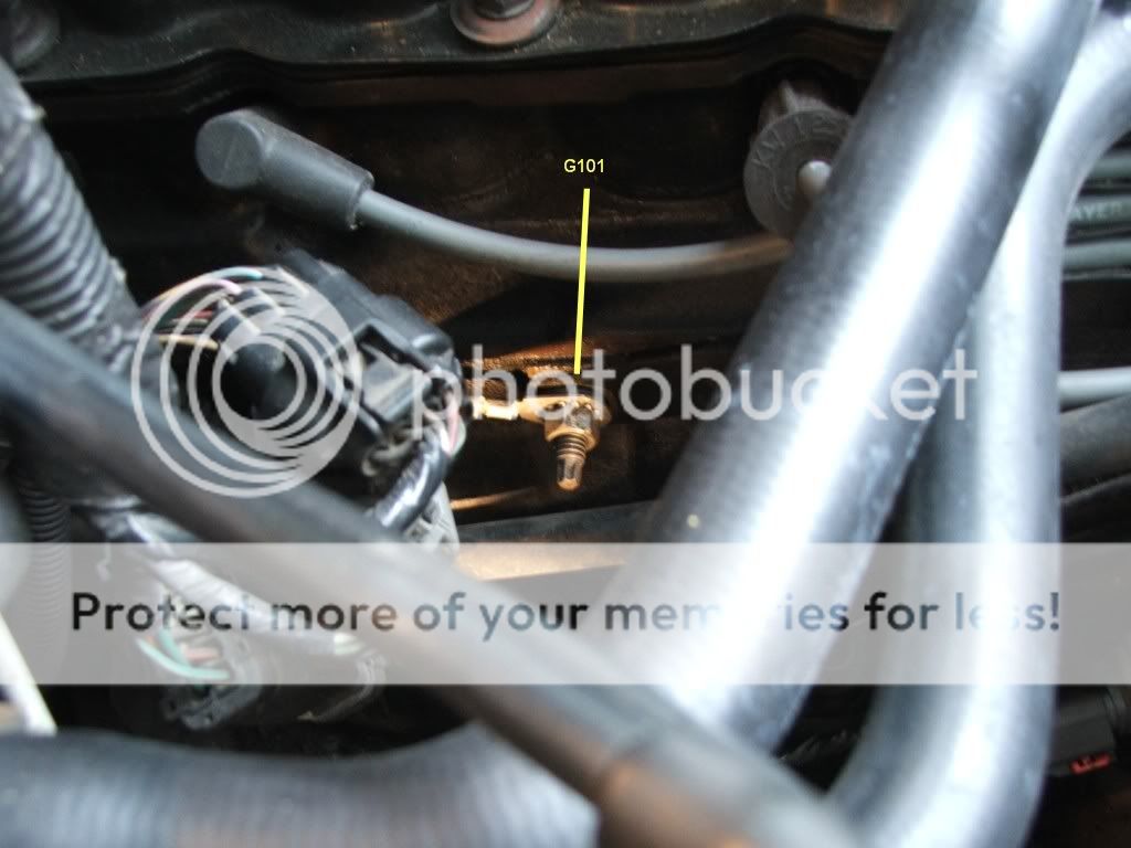
  • With KOEO, both heater and sensor grounds are ~0.4ohms. KOEO signal supply is ~4.04v, which is odd because I expected to see closer to 5v.
  • With KOER, signal supply starts around 4v but slowly drops during the first couple of minutes of runtime as the engine warms up. It eventually drops to negative .450v or so, where it then fluctuates +/- .050v for a few minutes. After another minute or two, the voltage spontaneously changes to negative .050v and the engine starts loading up on fuel.
Any idea what I should start checking next? I'd love to get this issue sorted out before the C4C...otherwise it'll be a long drive with that CEL staring me in the face.

Thanks in advance for your help!
 
The misfire doesn't feel like a single-cylinder situation. The chugging / stumbling seems pretty spuratic as though all the cylinders are intermittently loading up, but I could be wrong.
 
Just brainstorming....

*Verify oxygen sensor wiring and connector

*Get some actual gas mileage numbers so you have a baseline. Miles driven divided by gallons consumed.

*Verify fuel pressure with a gauge (49.2 plus or minus 5 psi is your target)

*Verify MAP sensor operation and that the vacuum line leading to it is actually pulling vacuum. Map is in play for fuel/air mix.
 
I've attempted to "verify" o2 sensor and wiring as best as possible and have gotten the results listed in my first post. I'm not sure what to make of them at this point. Today I am going to verify continuity along the O2 signal wire from the harness connector to pin A24 at the PCM. The low-ish KOEO reference voltage has me a little concerned.

Actual gas mileage has been in the 8-10mpg range with extended highway driving, and the truck spits raw fuel out the tailpipe at idle. It is undoubtedly too rich.

FP was fine at 45-47psig.

MAP sensor tested fine. I'm unsure what sensors the PCM defaults too when forced into open loop operation after the o2 sensor is disconnected, but all those sensors (TPS, IAT, CTS, MAP?) are working fine. I must emphasize that the truck idles and drives perfectly in open loop and that it's specifically closed loop operation that is causing all the trouble.
 
With the ignition off disconnect all sensors that are fed by a 5v reference. Connect one at a time and turn the ignition to on, but do not start until the reference voltage drops and either the sensor or wiring is the problem.
 
SteveX82,

Couple of questions:

I assume it's the upstream Oxy Sensor you are dealing with...correct?

How are you determining Oxy Sensor voltage outputs? With a scanner, or at the Oxy Sensor connector using a voltmeter?

My observations:


1. You said:
  • "a P0171 code in the '97 XJ that I just picked up. Gas mileage is awful and the exhaust is black, so it's obvious that the sensor is falsely reporting a lean condition when things are actually quite rich." and
2. You said:
  • With KOER, signal supply starts around 4v but slowly drops during the first couple of minutes of runtime as the engine warms up. It eventually drops to negative .450v or so, where it then fluctuates +/- .050v for a few minutes. After another minute or two, the voltage spontaneously changes to negative .050v and the engine starts loading up on fuel.
The FSM says P0171 "A lean air/fuel mixture has been indicated by an abnormallly rich correction factor."

(Remember, the Oxy Sensor voltage output is inversly proportional to the amont of oxygen it senses in the exhaust, i.e., Lean (high oxygen content)=Low Voltage, Rich (low oxygen content)=High Voltage).

I think the PCM is responding normally to an extremely low voltage output (lean) from the Oxy Sensor and commanding a richer mixture to compensate. In this case, the very low voltage output of the sensor, may be out of the normal output range of the sensor. The variable capacitor in the sensor has a normal output range of 0-1.00 VDC. The sensor looks like it's switching normally however.

This sensor may be defective.

If you don't already have one, I suggest you obtain a scanner that displays PID data while the engine is running. You can then determine the voltage outputs of the upstream and downstream Oxy Sensors and the short-term fuel trim response from the PCM.

I use one that does this: With the key in the Run postion and engine off, the Oxy Sensor outputs displayed are 1.00V; With the engine running the sensors display 1.00V while in the Open Loop mode, then they come on line the instant the PCM switches to the Closed Loop mode. At idle...The upstream sensor switches back and forth around .250V (normal 4.0L lean ops), and the downstream sensor switches back and forth around .850V (normal rich ops, showing the catalytic converter is holding the oxygen from the lean incomming mixture. During this operation, I can watch the PCM fuel trim outputs responding to the sensor outputs, trying to maintain a 14.7 to 1 fuel/air ratio. In your case, this is where you would see the abnormallly rich correction factor you are encountering (DTC P0171).
 
Charles: What other sensors are fed by 5v source? Downstream o2, MAP, and TPS? Just to be clear, are you recommending that I disconnect all these sensors and then monitor the KOEO upstream o2 signal voltage as I reconnect the other sensors? Do you think that there might be a short in one of the other circuits that's causing the voltage drop?


Sidewinder: Yes, this post involves the upstream sensor. O2 signal voltage is being read with a digital Fluke multimeter between the DG/WT wire at the O2 connector and battery ground.

I'll ask around and see if any of my friends has a scanner that I can borrow, but I hope I can diagnose this the "old fashioned" way with the DVM. I think Charles may be on to something with this unusually low 5v reference signal.

FWIW, continuity checked out between the DG/WT o2 connector pin and pin A24 on the PCM at about 6ohms.....this seems a little high to me as I didn't notice any resistors inline between the two test points.

Thanks for the quick replies, guys! Keep them coming!
 
SteveX82,

The Oxygen Sensors are not fed a 5VDC supply voltage like other sensors - they are stand alone systems, generating their own voltage from a variable capacitor located inside that 'can' on the sensor.

Edit: Just realized what you are reading. The DG/WT wire at pin 1 of the sensor (harness side) connector is 12VDC power for the sensor heater. Power comes from fuse #23 (via the ASD relay) in the Power Distribution Center. Pin 2 (BK wire) of the sensor (harness side) connector is ground for the sensor heater. The ground is G101, located at the engine oil dipstick tube support bracket attachment.

Sensor connector pins 3 and 4 are the sensor signal wires. Pin 4 (BK/DG) is the sensor output voltage signal to the PCM, pin 4 (BR/YL) is the sensor ground (inside the PCM).

If you are reading low voltage at pin 1 (DG/WT) wire at the harness side connector to ground, check fuse 23 for corrosion in its pin connectors; If fuse 23 is defective, the downstream Oxy Sensor would be affected as well. If the ASD Relay was defective other functions, such as fuel pump and injectors, would also be affected.
 
Last edited:
SteveX82,

The Oxygen Sensors are not fed a 5VDC supply voltage like other sensors - they are stand alone systems, generating their own voltage from a variable capacitor located inside that 'can' on the sensor.

I presume that means I've got a short somewhere along the BK/DG wire... Are there any particular closely-routed wires that I should disconnect one at a time while troubleshooting?
 
I must add...

There is no valid way of testing the output of an Oxy Sensor with its connector disconnected. With it disconnected, there is no power to the sensor heater. The sensor will not function properly without the heater operating. The only checks you can make with the sensor disconnected are:


1. Check power to the sensor heater:
  • With the sensor connector disconnected, on the sensor connector harness side, place ignition swith to run, place the red lead of the voltmeter to pin 1 (DG/WT) and the black lead to pin 2 (BK). You should read battery voltage (12 VDC).
  • If less than battery voltage, leave the red lead on pin 1, and place the black lead to a good engine ground. If battery voltage is read ground G101 is bad, or wire BK is bad. If a bad wire is suspected you'll need to check resistance between pin 1 (DG/WT) and G101. See previous post about fuse #23 if power lead (DG/WT-Pin 1) is suspected bad.
2. Check sensor heater (you are reading the resistance of the sensor heater):
  • On the sensor connector (on sensor) there may be two white wires if it is an after market sensor, Select 2K on you Ohmeter, place one lead to a white wire pin and the other to the other white wire pin, you should see some resistance (.002 Ohms). If not, the heater element of the sensor is bad. Replace sensor.
Most Oxy Sensors have a warranty. With your problems, I would just
replace it with another one.

Pic of G101

DSCF2141.jpg
 
Thanks a million for all your help, Sidewinder. From what you describe so far, it seems to me that seeing +4.0v on the BK/DG wire with the harness disconnected is a problem. I must have confused this reading with my experience with wideband sensors where a 5.0v reading isn't abnormal.

The heater power reads 12v and both heater and signal grounds read great (less than .4ohms). Resistance across the sensor heater pins read about 4ohms. These readings suggest that the sensor itself is ok.

FWIW, The downstream signal return wire reads 0v. Unplugging either the "A" connector at the PCM OR Fuse 21 at the PDC cause the KOEO voltage on the BK/DG wire to drop to ~0.500v.

Do I have any choice besides unwrapping the harness and tracing this o2 signal wire all the way back to the PCM to find the short? I've unplugged every other connector I could easily spot, but only the two aforementioned connectors made any difference.
 
Cavity A23 on the PCM connector C1 is the TPS singal, which is adjacent to cavity A24. With KOEO, it could be that the TPS 5V (or part thereof) supply is shorting accross to cavity A24 at the PCM connector C1. Pull the connector off the TPS and see if the voltage on cavity A24 (BK/DG) goes away. The Oxy Sensor BK/DG is a straight shot from the Oxy Sensor connector to the PCM C1 connector, with no splices in between, so I would look for a short in one of the connectors before tearing the harness apart.

I forgot to ask... are you reading voltage at both ends of the BK/DG connectors, with both connectors disconnected?
 
With both connectors unhooked, there is no voltage at either end of the BK/DG wire. As soon as I plug C1 back in, however, I get ~4.23v at the o2 end. I'm unsure what the C1-end of the wire reads when connected as I haven't tried backprobing, but I can only presume that it also reads 4.23v.

Voltage on the BK/DG wire remains even after disconnecting the TPS (and the MAP, and the IAC, etc). The only ways to drop the voltage so far have been disconnecting connector C1 (which results in 0v) or pulling fuse 21 at the PDC (which results in ~0.500v and scares the living bejesus out of me, as it turns on the electric fan). Does this fuse in any way power the o2 heaters?

I have checked for continuity between the o2 sensor end of the BK/DG wire and all of the cavities on the C1 connector and have come up empty, so it looks like the BK/DG wire isn't shorting against anything in that particular harness. I'll check the remaining two connectors at the PCM after work tonight.

FWIW, the truck had a pretty significant power steering leak that coated the upstream o2 harness in fluid pretty badly. I sprayed out the loom and connector the best I could with contact cleaner, but it would probably be a good idea to test that the connector itself isn't causing a short to the o2 heater supply wire...
 
Back
Top