• Welcome to the new NAXJA Forum! If your password does not work, please use "Forgot your password?" link on the log-in page. Please feel free to reach out to [email protected] if we can provide any assistance.

ELK-960 fan timer questions

anthrax323

NAXJA Forum User
Location
San Antonio, TX
Hey guys,

I know several people have installed an ELK-960 fan timer to solve 2000 and 2001 heat soak woes:

http://www.at-fairfax.com/P1786-ELK-960.htm
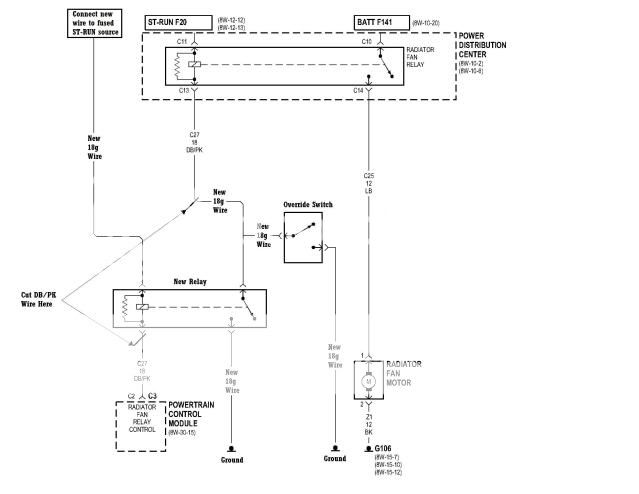
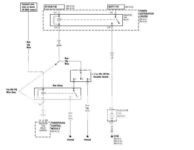
Hell, it actually looks like fellow NAXJA'er muddeprived drew a pretty good schematic regarding how to wire it in:

http://i37.photobucket.com/albums/e73/muddeprived/cherokee/AuxFanDelayTimerWiring.jpg?1286206881

My question is this: why can't the timer be used as a secondary trigger for the factory relay? I'd like to avoid adding another relay and high-amperage circuit to the vehicle's electric system and simply piggy-back on the stock/existing e-fan relay. Am I overlooking anything in this idea?
 
You should be able to figure it out.

You would want to use diodes to prevent any feedback to the PCM.
 
Thanks Joe, I was thinking that might be necessary (though I'm rusty on what I learned in my brief run with ECE at UIUC). I assume I'd need to put a diode on each trigger going into the factory relay - one on the new trigger lead (timer) and one on the stock/PCM trigger lead?
 
FordGuy - I believe you may have skimmed this a bit too fast. The solution that I've seen thus far uses an additional relay, however, this thread was asking about whether or not it can be accomplished using only the factory relay for the sake of simplicity. Thanks for the input, though :p
 
Yes it could.

The factory relay is done "ground side switch" style so you would want to do this:


I cannot guarantee that it won't set off the CEL as I haven't thought it through all the way (though it probably will not), so try at your own risk. It should function quite well however. You should use diodes with at least a 50V PIV rating and 1-2 amps forward current rating, I would probably grab a 1N4001 (or any other 1N4000 series up to 1N4007, radio shack sells an assortment of them for a very reasonable price) or 1N5400 to 1N5408 series depending on what I found first in the parts bin. 1N5819 Schottky diode would probably also function fine but is completely unnecessary and harder to find without ordering online. I only use those sometimes because I got a huge sack of them for free a while ago and sometimes find that bag of parts before the 1N4000 series bag.
 
Rock the hell on - thank you man! Now I need to find a friend with an oscilloscope for some bench testing, or bite the bullet and renew my TechShop membership to get this underway :D

How sensitive is the PCM? That is, would an underrated diode risk any damage to the unit?

Also, a side note - are the diode symbols backward in that diagram? I always though the arrow pointed in the direction of the current... Then again, I see you mentioned that the factory relay is a ground side switch, which may explain my stupidity in this case. Would the ELK-960 even work in such a scenario, seeing as the timer's trigger would be a current source?
 
The PCM has solenoid/relay drivers in it, so it should handle things just fine. An underrated diode will just fail prematurely.

(begin electrical engineering nerd crap)
The diode symbols are "backward" in that diagram for that reason - with the ground side switched design, effectively the relay coil is always powered from the "top" end with 12 volts, and the PCM turns it on by grounding the other side, completing the circuit. This is done for a few reasons - first, N-channel MOSFETs and NPN BJT power transistors are generally available for cheaper (for the same voltage/current handling capability) than P-channel or PNP transistors, and N-channel or NPN transistors function best in a ground side switched configuration, otherwise you have to do annoying level shifting / charge pump setups to control them. Second, they preserve logic state polarity - i.e. the ECU electronics send a "1" bit (i.e. a logic "high" voltage) to the signal wiring that triggers the relay control transistor, which responds by turning on and grounding the low side of the relay coil, which turns the coil on. So the logic is only "inverted" between the transistor and the relay coil.
(end electrical engineering nerd crap)

I'm not sure if the ELK-960 works with that setup, haven't looked into it very much. Hopefully it has a polarity inversion jumper/DIP switch setting that allows you to set the output polarity however you need it.
 
Yeah, looks like that should work perfectly. Make sure you use the diode network I drew above or I can almost guarantee you'll get a CEL the first time the timer turns the factory relay on - the ECU would see this as a shorted relay driver or open circuit in the relay coil + wiring. After thinking about the diagram I drew, I can't think of a case when it would cause a CEL, it should isolate the two relay control circuits quite well.
 
Makes perfect sense, through and through. Thanks a ton buddy, as always your wisdom is sincerely appreciated!

I, too, don't think it'd risk triggering a CEL as the fan timer will switch off (open) upon signal state change (hot to cold or vice-versa depending upon its configuration). Hell, if both were open simultaneously, given that it's a ground-side switch I still don't think there would be an issue if both circuits were closed.
 
Crap, just realized we may have overlooked a crucial detail... Is the electric fan power source switched or constant? Maybe there's a reason everyone puts in a new fused power lead and secondary relay...
 
:dunce: good point, checking 98 FSM now.

EDIT: according to my 99 FSM (left the 98 FSM in my car in the parking lot, too lazy to walk outside...) the radiator fan relay is powered by the battery via circuit F141, which is sourced from a 40 amp fuse in position 5 from circuit A0

The relay coil is however powered by start/run power on circuit F20. F20 is powered by fuse 10 (15 amps) off start/run circuit A21, which is only powered in start/run... can't just wire this to be constantly powered, because it also powers the evap LDP, evap purge solenoid, NSS, AC compressor relay, and DRL module.

I can't guarantee that it won't result in the fan always being on when the vehicle is off, but you can try disconnecting the relay coil power wire (should be white) from the start/run powered circuit and connecting it to the same power wire feeding the switch side of the fan relay (should be light green with a red stripe.) To test this without hacking up the wiring harness, unplug the fan relay, find a spare, bend the terminal for the coil side of the relay up around the side of the case*, solder a small wire to it (even 20ga telecom wire should be fine for test purposes) and solder the other end to the very top of terminal 30 (the large terminal furthest from the side of the relay with 3 terminals.) Install the test relay, if the fan immediately turns on with the vehicle not running, this method won't work and you'll need a second relay, else you can splice the wiring harness under the PDC as outlined above.

* should be the one that is connected to start/run power, not the one that goes to the ECU. It's pin 86 as shown in this diagram: http://www.wiringdiagrams21.com/wp-content/uploads/2009/04/jeep-wrangler-tj-horn-relay-diagram.png
 
Last edited:
They're probably the right manual but might not be, and they are probably pirated material. Paying for pirated material is in my opinion even worse than just pirating it yourself.

Updated previous post with more detailed info.
 
That was actually my wiring schematic you posted above. I didn't actually use it (or any of the variations of it in that thread) as I have no need for the timer. I was just helping out. I believe others used it with success though.

I have my auxillary fan wired up so that I can control it via the factory relay. It's been awhile since I did this mod so the details of both the timer and my override switch are fuzzy in my head. Maybe you can combine the two to make it work. Here's the schematics from my override switch thread:

Force on only-
AuxFanWiring2.jpg


Force on or off-
AuxFanWiring3.jpg


I figure you could wire it up so the timer replaces both the "Override Switch" and the "New Relay" in my first schematic. The only thing I see as a potential problem is that I believe the timer and relay share a power source. The integrated relay needs to be able to gound the factory relay and I'm not so sure it can do that while also providing power to the timer. Wish I could give you better direction, but as I mentioned, it's all a little fuzzy as it was a few projects ago...
 
Last edited:
Back
Top