- Location
- In a strange land
Project Scope Creep (alfred): Rear Axle Swap turned into Shackles&Relocation Brackets
Preface: This probably old hat to the experienced crowd here. For those who don’t want to be bored with the details, if you skip to the end I could appreciate some advice regarding the driveshaft angle, the speedometer sensor plug and shock absorbers. Thank you.
I thought the Thanksgiving weekend would be a good time to tear into what I hoped would be a quick project: Swap out my 3.07 geared 8.25 rear for a 4.10 geared 8.25. Should be a simple, straight up R&R type job. Right?
Well, just about exactly one month later I am finally able to drive my XJ around the block again. So much for my hopes. Oh well. False hope is still hope. But I did learn a couple of things in the process. Largely about what doesn’t work, but hey, that is a start, right?
3.07 gearing is pretty pathetic. And I didn’t get lucky enough to have my ’96 come with a 29 spline axle. A Dana 44 would be nice, but they don’t seem to grow on trees. However, I found a free Chrysler 8.25 on C/L, got a 29 spline factory Trac-Loc carrier from a fellow member for the price of a couple six packs of beer, and a pair of Ten Factory 29 spline shafts were obtained from another member for about half the price of new. That seemed like a good starting point for an upgrade.
I dropped off the parts at a local shop and had them provide the gears and full bearing kit. I also gave them an Iron Rock Offroad U-bolt yoke and a crush sleeve eliminator. When I picked up the axle they told me they chose not to use the crush sleeve eliminator because it did not register properly on the lands and they thought it would cut through the shims. I was not happy about this. I wish they would have called me at the time they found the problem. I could have turned a new sleeve of my own to whatever dimensions they wanted. Oh well. Next time.
The axle got wire brushed with an angle grinder, primed and painted.
The free axle came with a box of brake parts, both for it and for the previous owner’s replacement axle (I think a D44—certainly not another Chrysler 8.25). It was a mixed up mess, and the brake shoes and drums were soaked with gear oil. I decided to simply order all new brake components. Slave cylinders, spring kit, shoes and drums were all ordered.
Additionally, for some reason, the new axle was missing the brake lines, so I ordered a replacement set of lines from Fine Lines and a YJ flex line to deal with a previous owners solution, i.e. to simply remove the hard line from its bracket and just let it hang in free space. Yeah, that is a long term solution. :looney:
I figured I should be good to go.
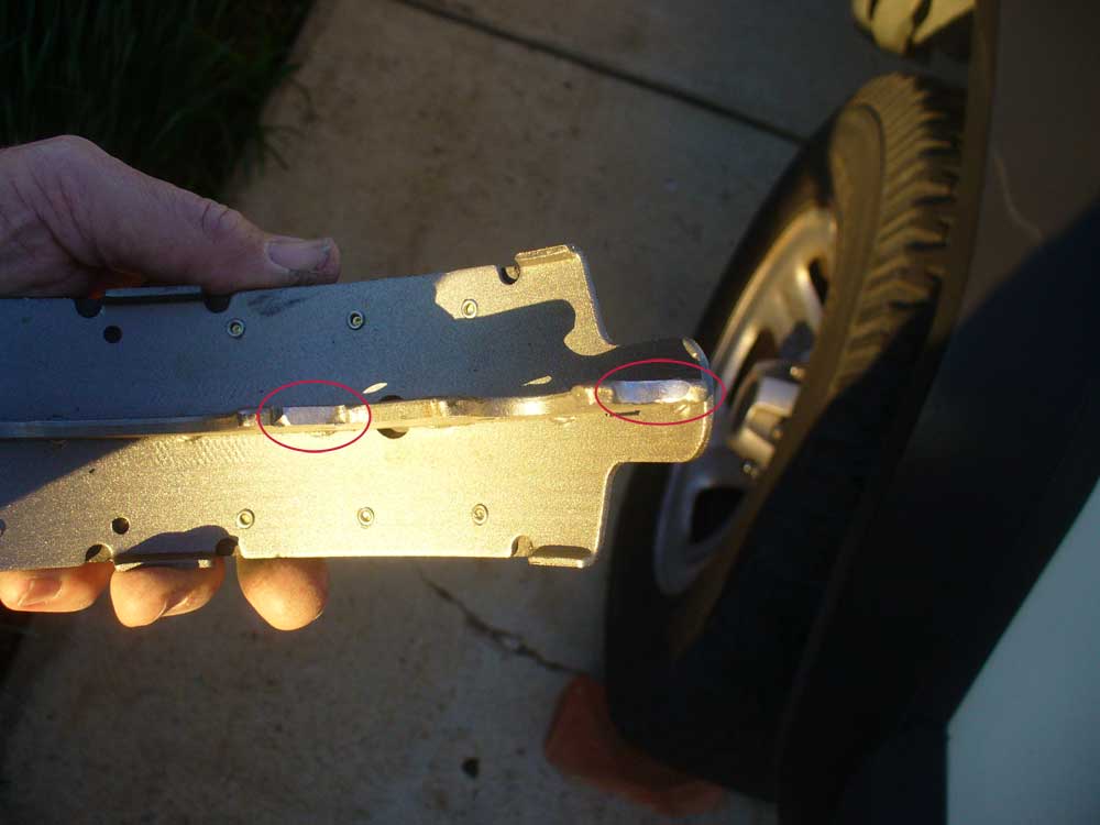
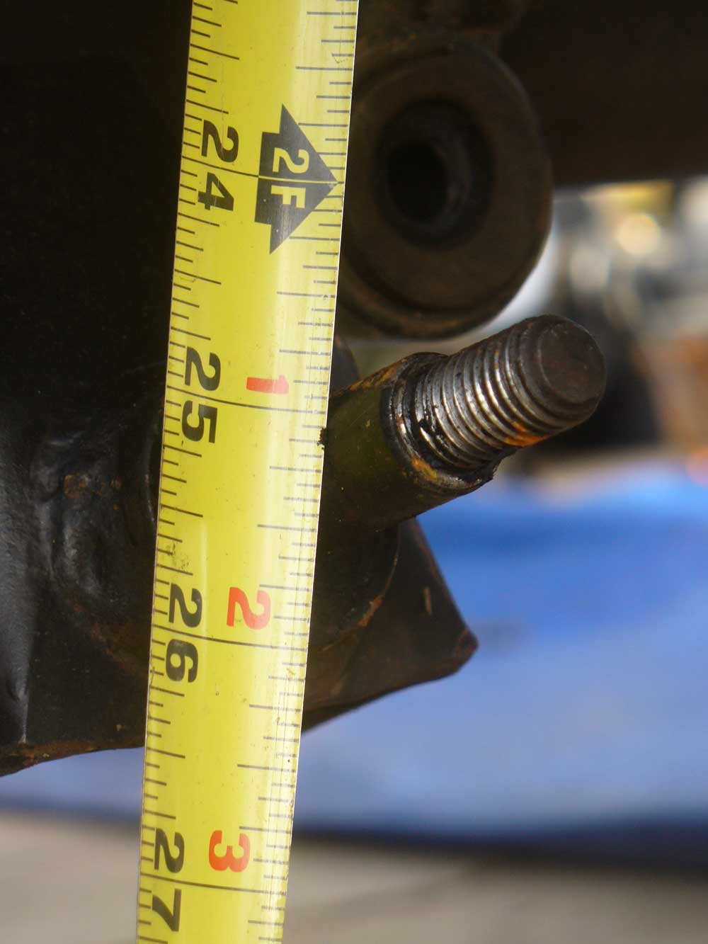
[FONT="]Friday morning, after Thanksgiving I tore into things. Just getting into the job and then this happened:

[/FONT] Well, phooey. I hadn’t planned on needing new U-bolts. Yes. My mistake. I now know better. One thing learned.
The nice thing about Black Friday is that pretty much all local retail is open. I would have thought it would be no problem to run out and pick up another set of U-bolts, but the only place that admitted to having anything in stock for an 8.25 was Napa, and with them it was “Bring in what you have and we will try to match it.”
Well, they could match the diameter (for the axle tube), but not the length. What they had to offer was right about the length at which that one side snapped off.
Okay, fine. I had been wanting to ditch this stack of blocks and shims ever since I bought the Cherokee. It was time change this out to something better.
[FONT="]For some time I had been looking for a leaf spring pack that would net me 3” or so of lift, then I saw this thread about combining shackle relocation brackets and longer shackles to yield the same effect
http://www.naxja.org/forum/showthread.php?t=1134237
[/FONT] I have seen a number of threads and comments bemoaning the pleasures of dealing with the factory hardware for the leaf spring mounts. I already liked the idea of switching over to HD Offroad Engineering’s Shackle Relocation Brackets. Getting a bit of lift that way sounded like good sense to me.
Additionally, I had seen Boostwerks’ Comp Shackles thread in the vendors section and really liked the concept.
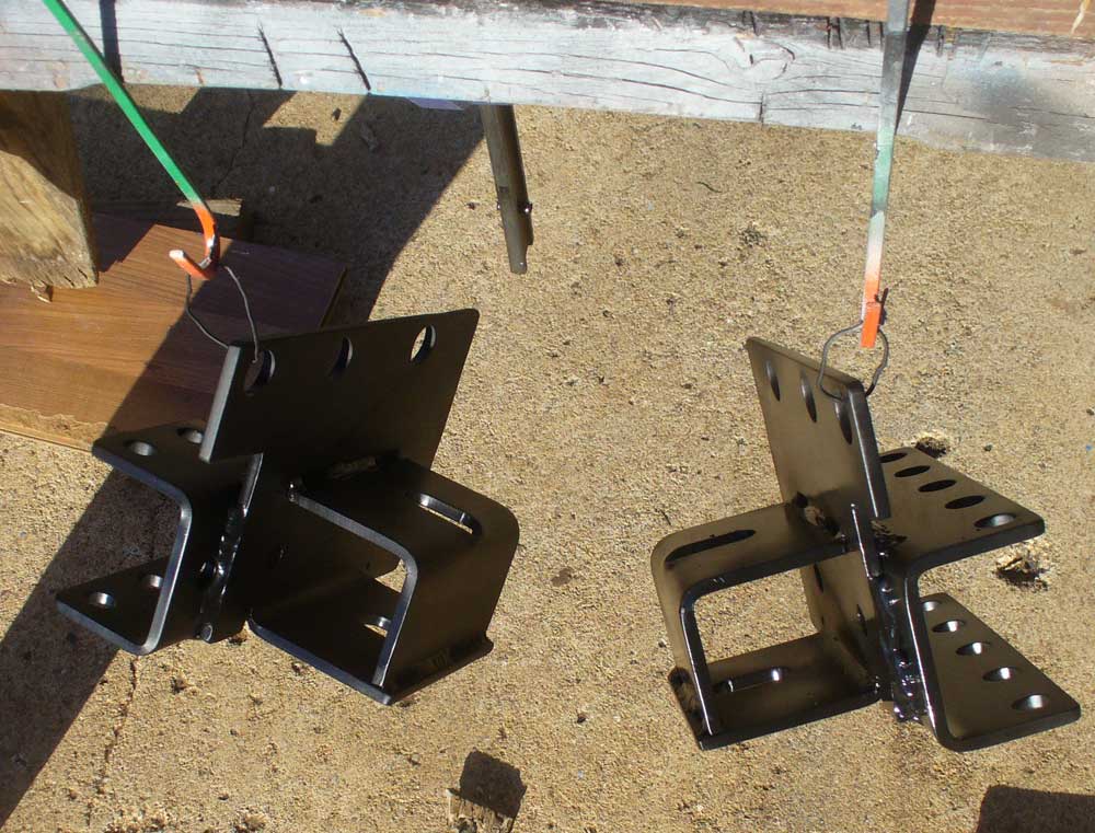
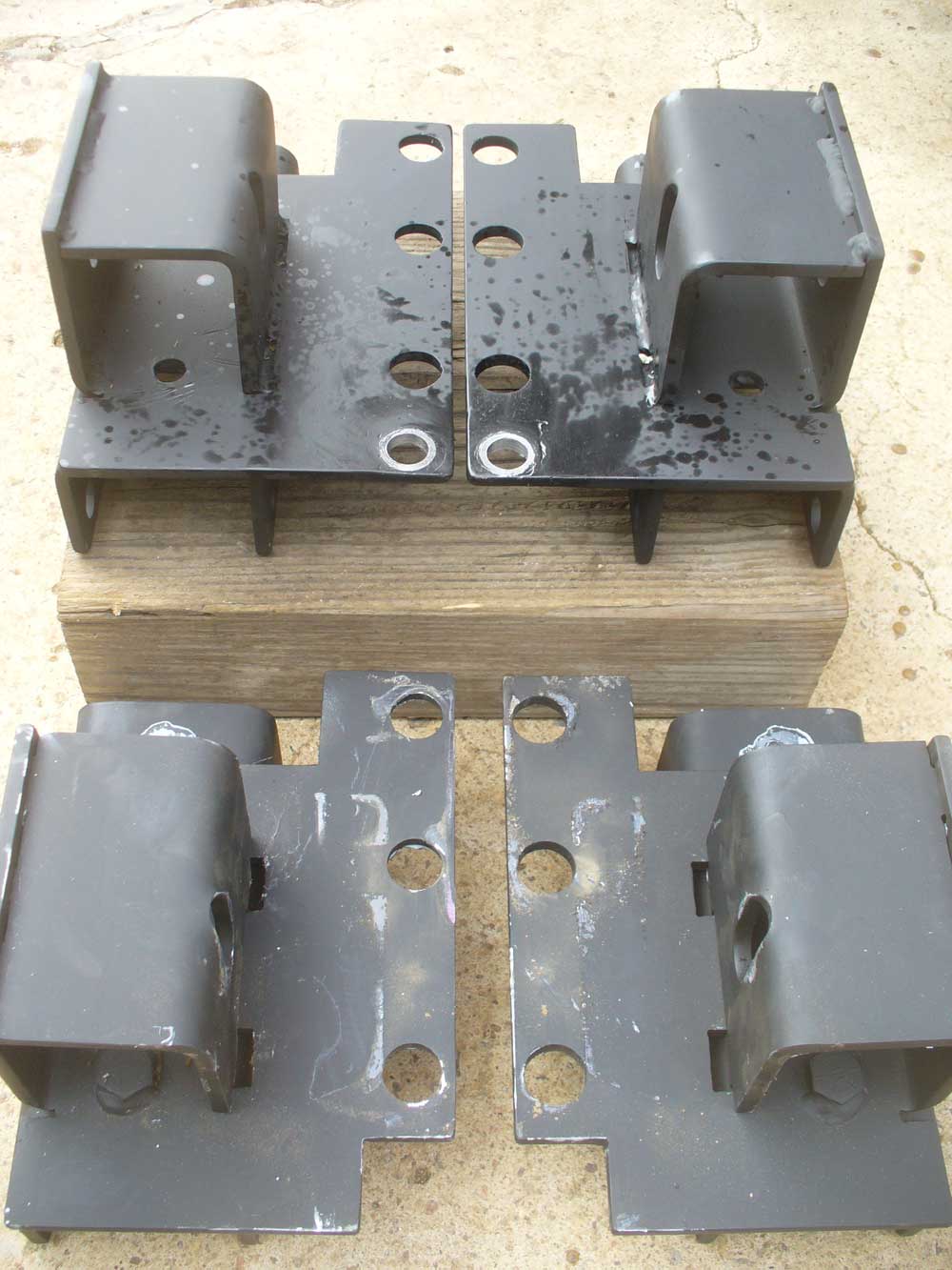
Relocation Brackets and Shackles had both been ordered and were on hand. Parts just weren’t quite prepped though.
Even for just a rattle can paint job I hate leaving hard corners. They don’t paint well and they do wonders to my knuckles when I find them the hard way. I went over everything with a file before giving things a quick sanding, priming and paint job. Even the new U-bolts needed to be painted (Napa’s U-bolts are bare, not zinc plated). That slowed progress down for most of a day. But I did have time to pull the rear bumper and hit the OEM shackle bolts with Kroil. And say a prayer that those bolts would come out gracefully.
The next day I got to move forward from where I was when the U-bolt snapped. The old axle was supported in place on three cheap mover’s dollies from Harbor Freight (I decided my back was more worth the $30 investment. That is a decision I would not have made when I was in my twenties.)
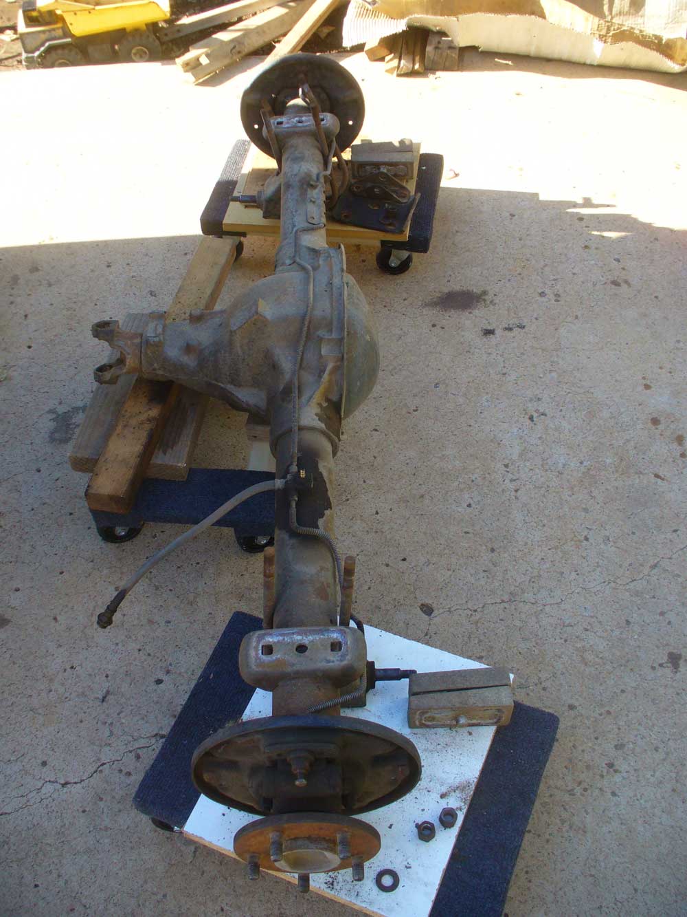
The new axle was then swapped with the old on the dollies, keeping the same arrangement so that things could slide into place gracefully.
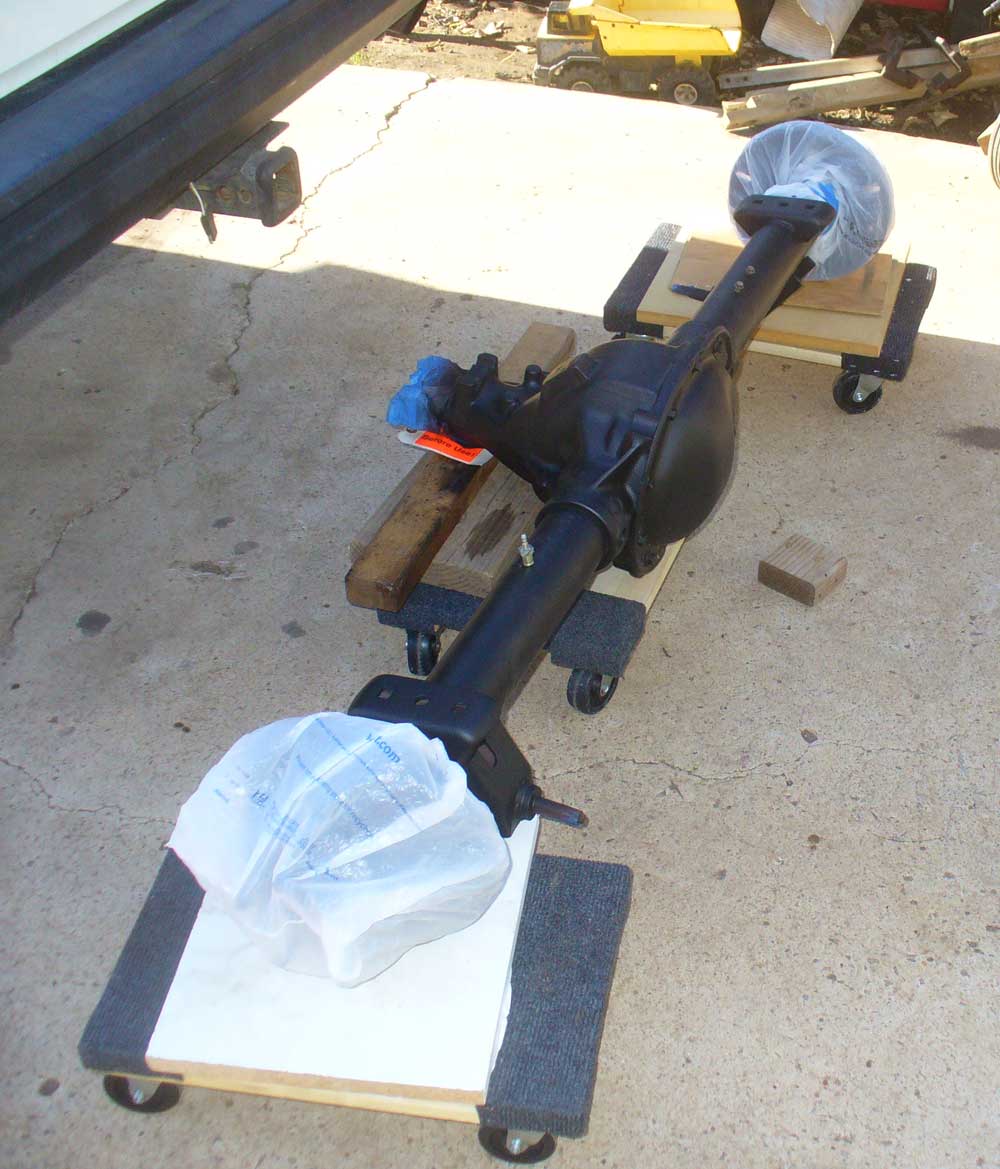
Some new brake lines got installed on the axle at this point. I didn’t want to put them on earlier for fear of mangling them while moving things around, but figured there was less risk now that the axle was on dollies and it would be easier now than it would be once the axle was in place.
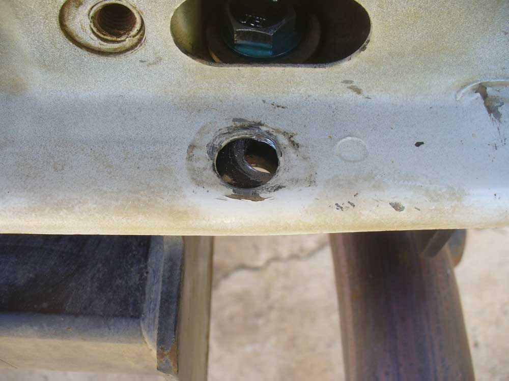
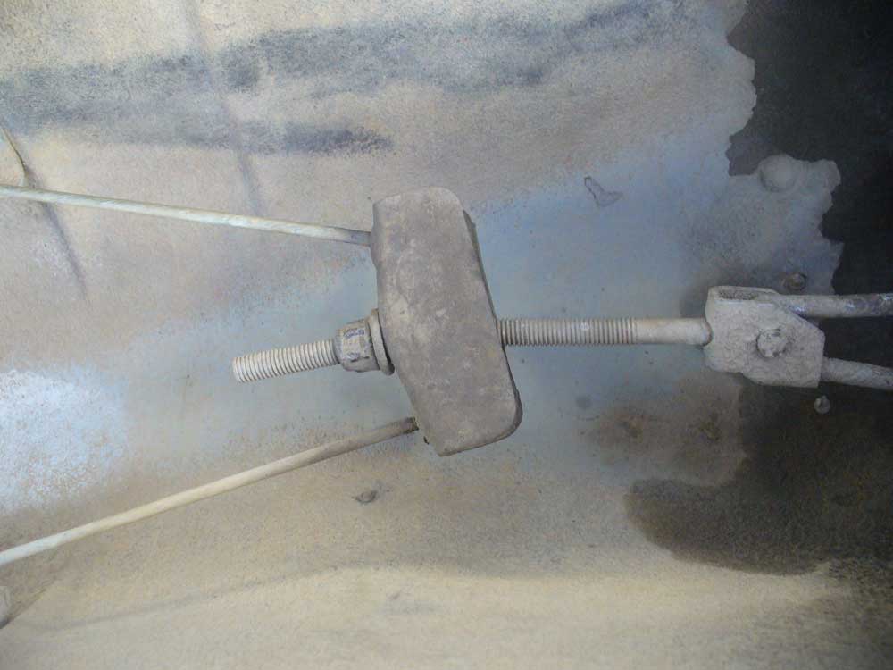
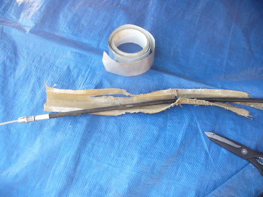
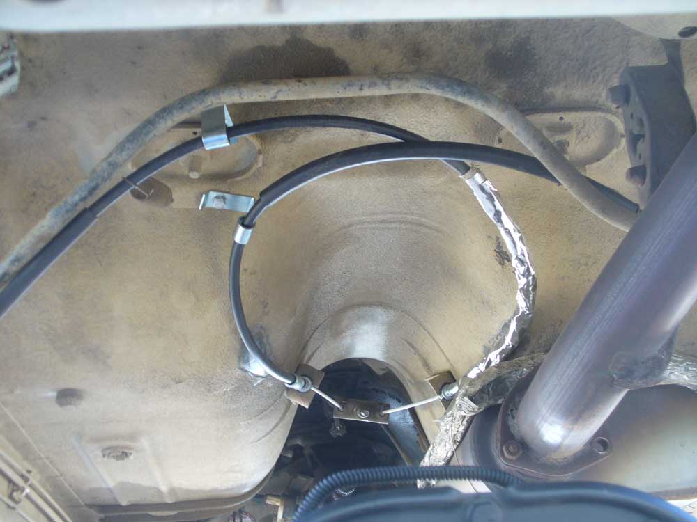
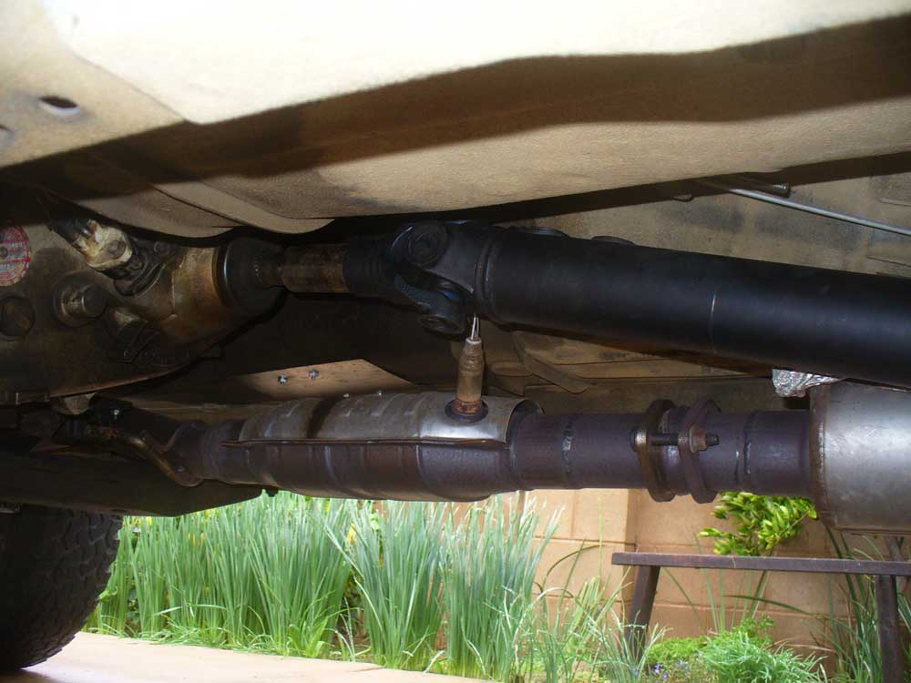
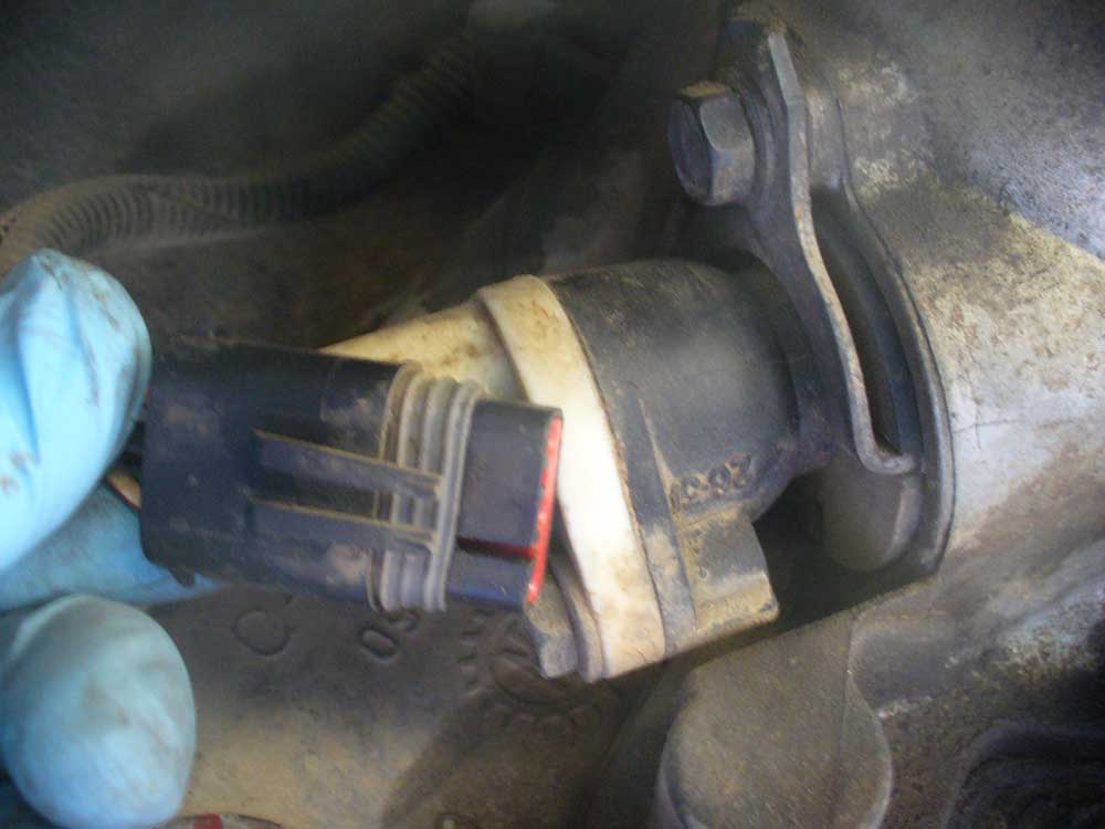
Previously, in order to compensate for the bit of lift from the blocks, someone decided to remove the hard line from its support bracket and allow for some extra freedom of movement:
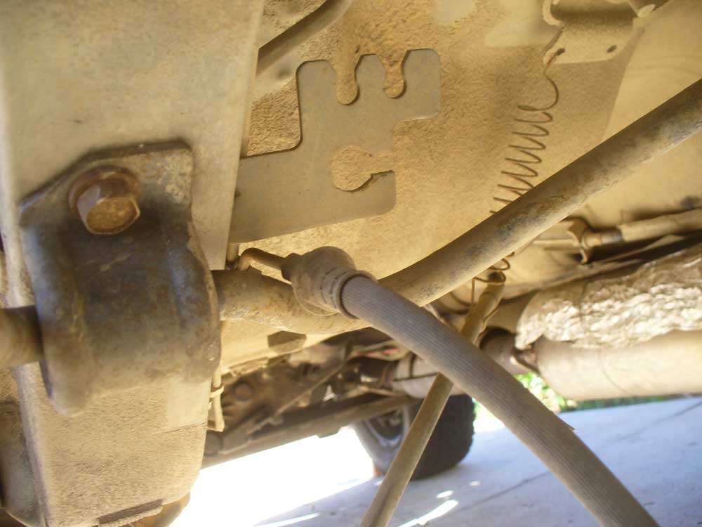
I can just imagine the surprise problem when the hard line finally cracks. I had already ordered a hose for a ’90-’95 YJ to take care of that little detail.

The new axle did not come with the old hard lines, so I ordered a new set of those from Fine Lines.

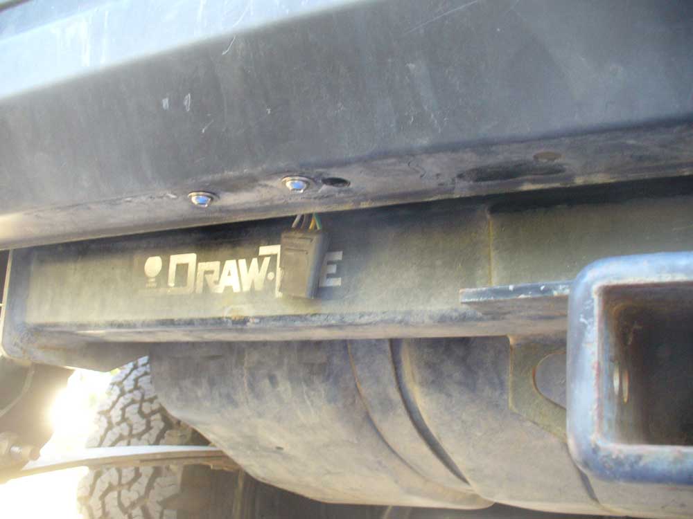
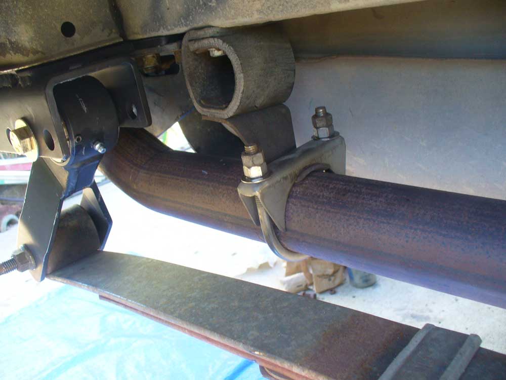
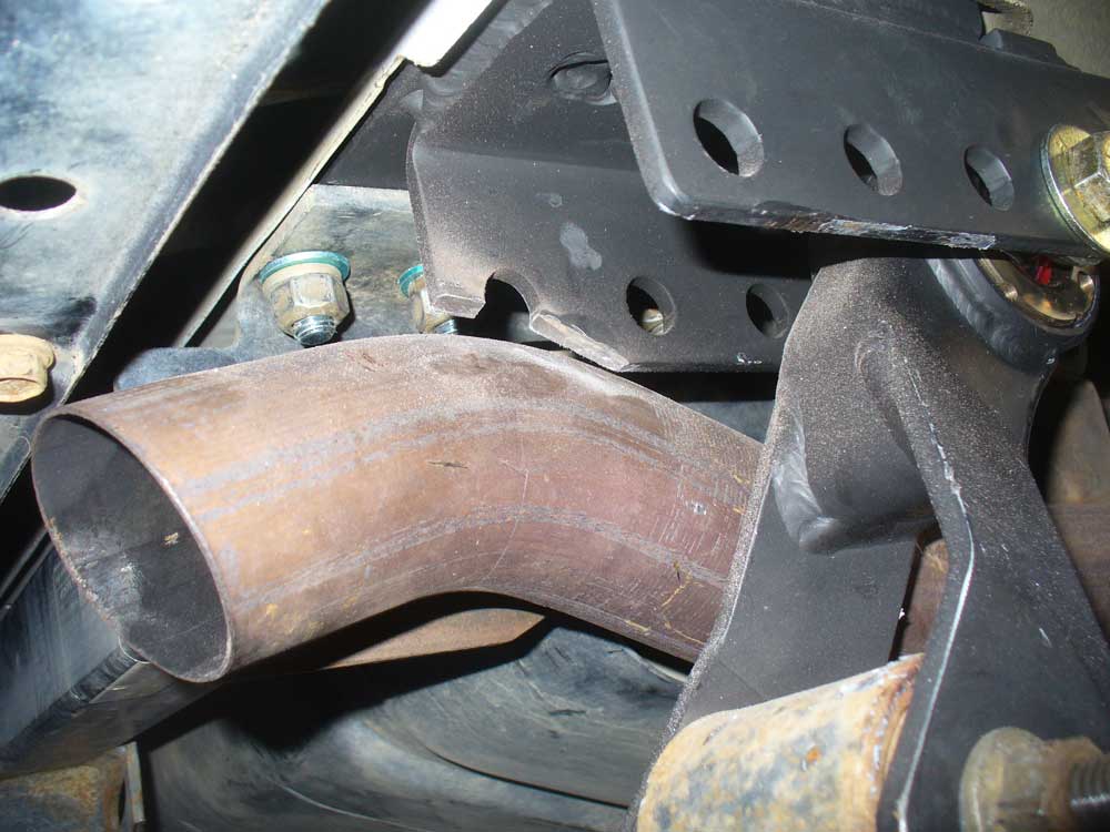
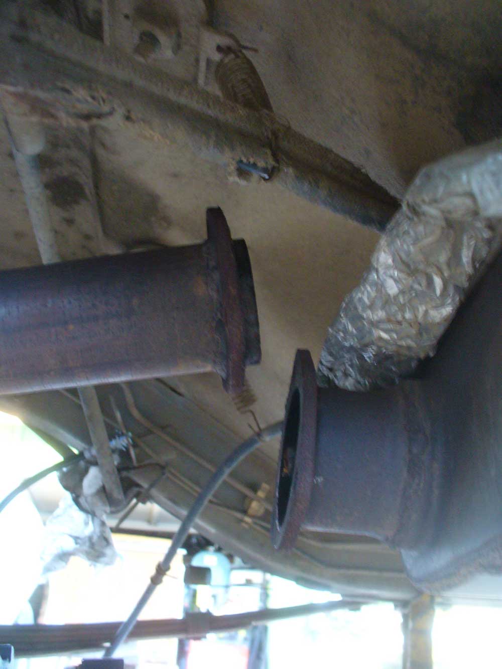
And then I also needed to get the exhaust out of the way since I was going to have to access the hardware for the receiver. I had anticipated needing to do this someday. When I redid my exhaust system I flanged my muffler/tailpipe joint. That was a big help.
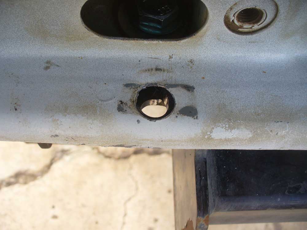
Finally it was time to go after those evil bolts. Kroil, prayer and a life without salted roads makes a difference. No problem at all getting those bolts out. They hardly even looked bad.

And the pockets looked fine too.

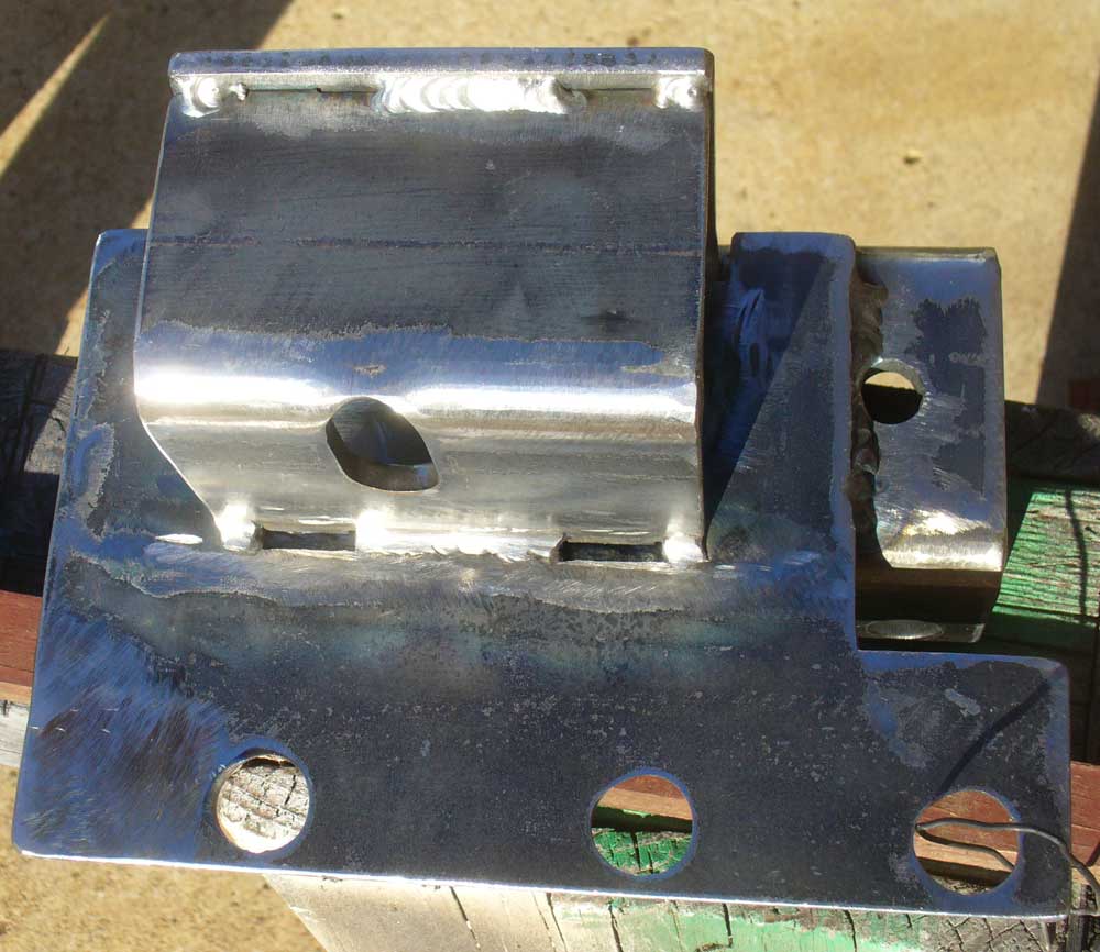
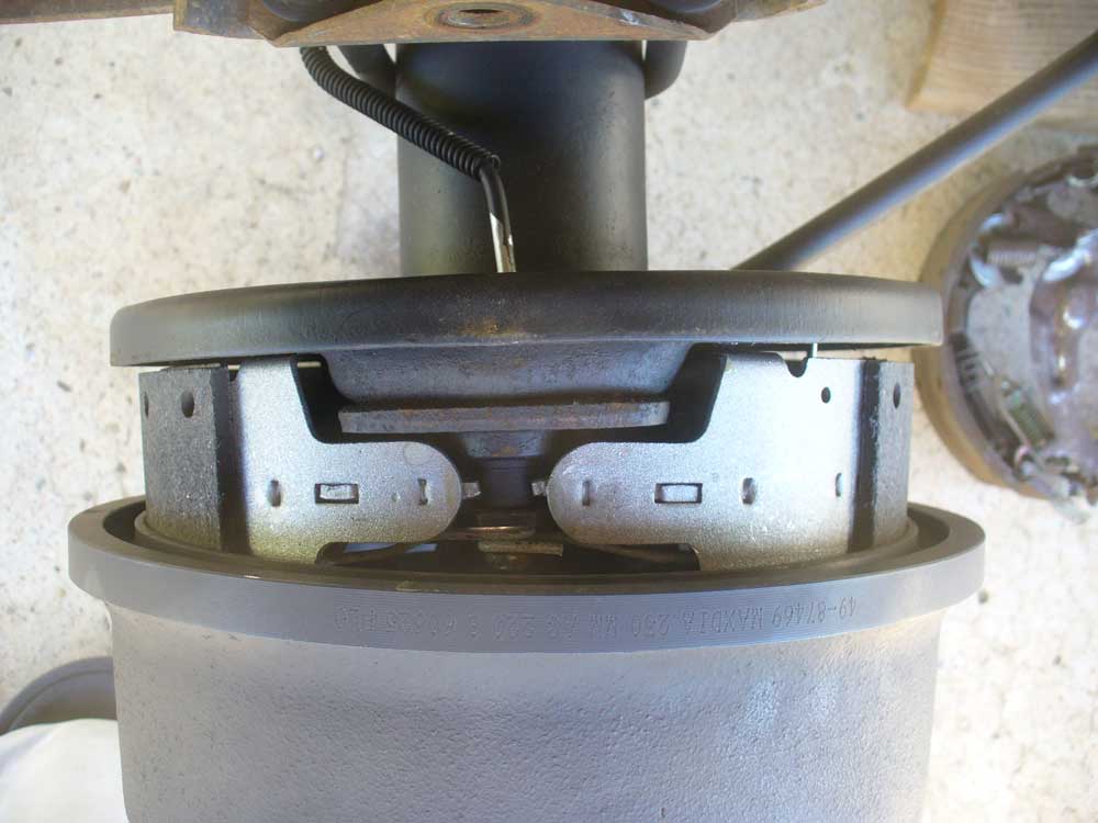
The shackle relocation brackets went in without any fuss. They are a nice snug fit, and a few blows from a mallet helped seat them. Pretty much exactly what I want in a fit.
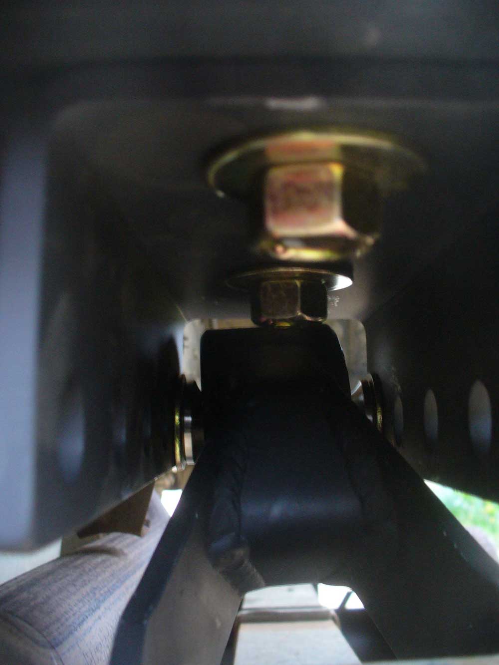
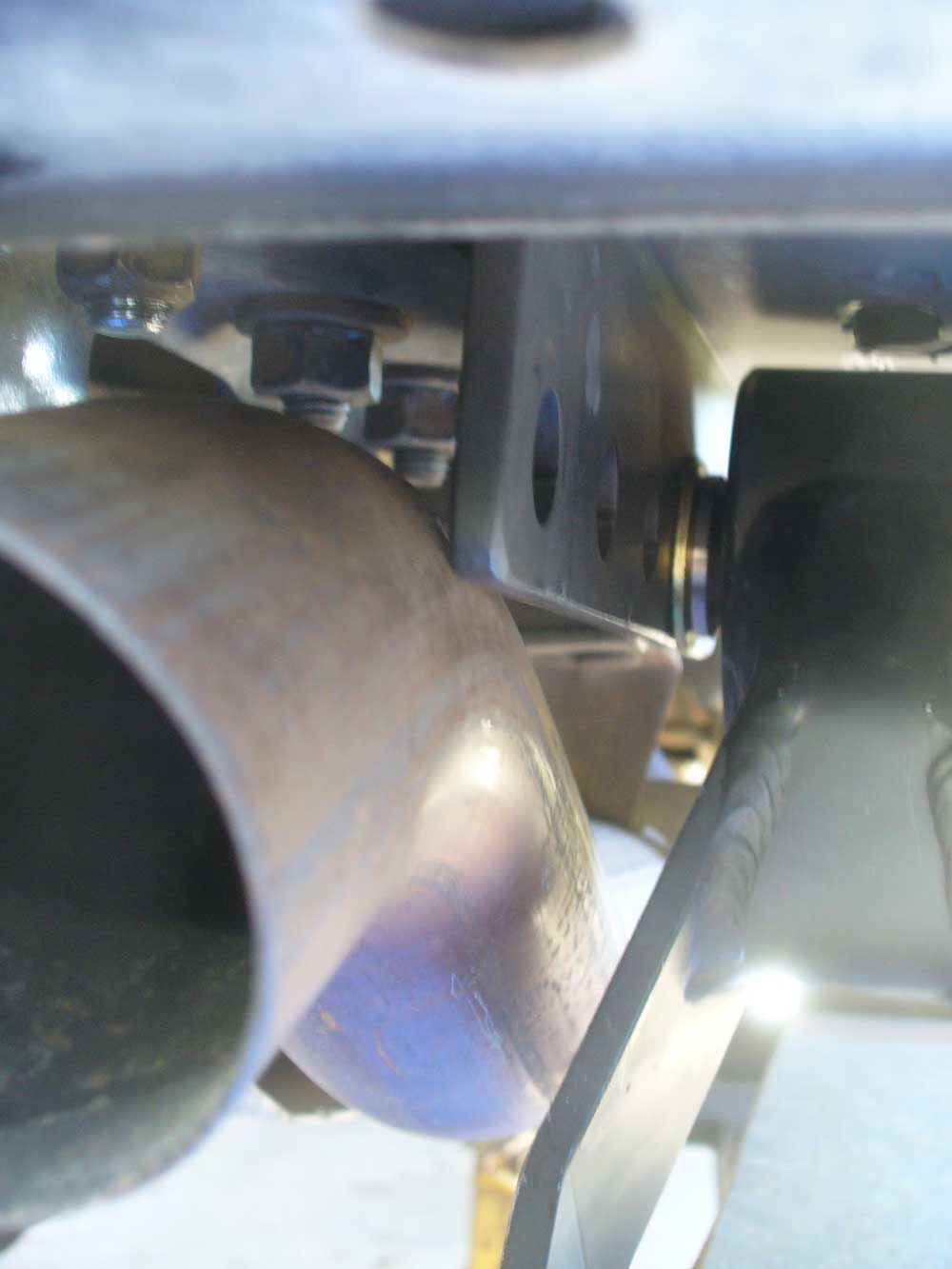
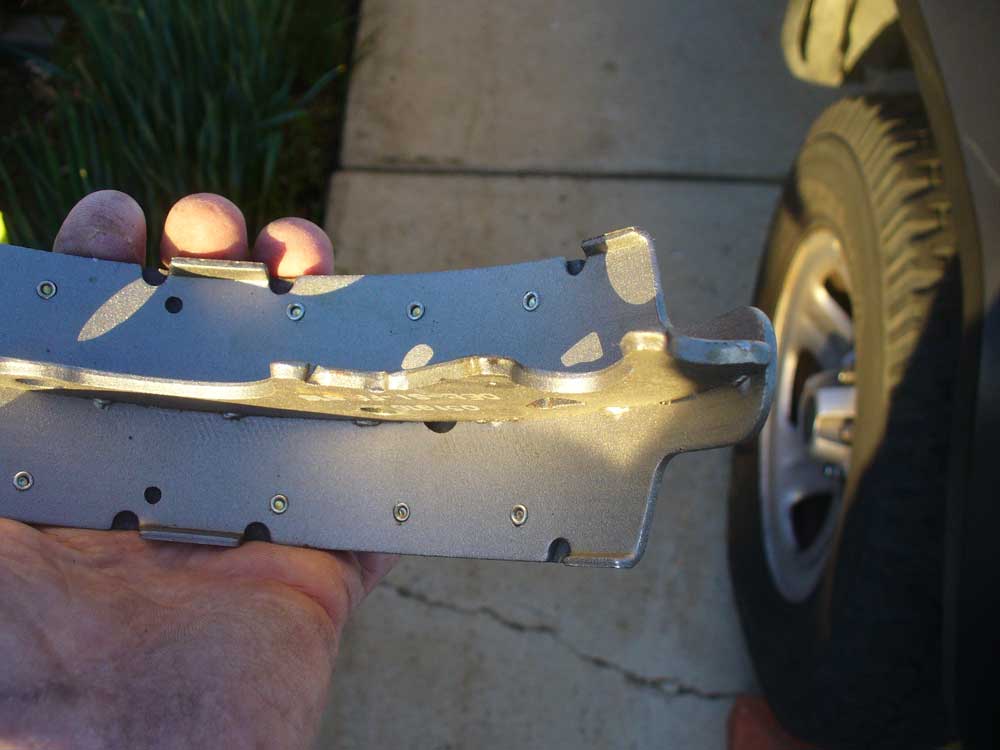
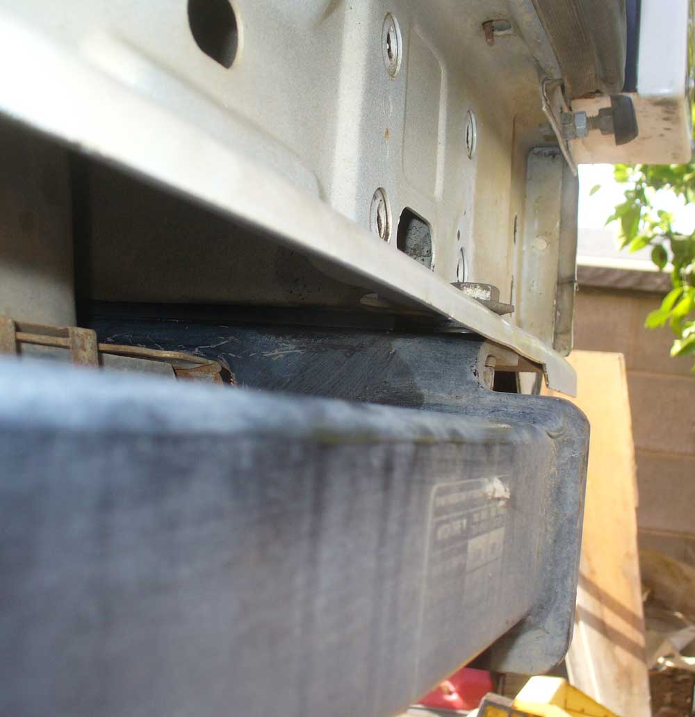
I understand the ’97 and up XJs have something different going on at the very back which requires that the one corner be notched out. I had to do something to make up for that on my ’96 because my receiver needs that support there. I found a stack of three 7/16” washers was a pretty close match to the ¼” plate.
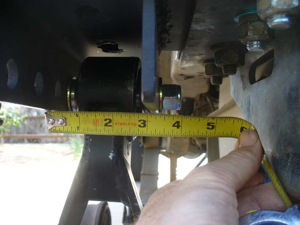
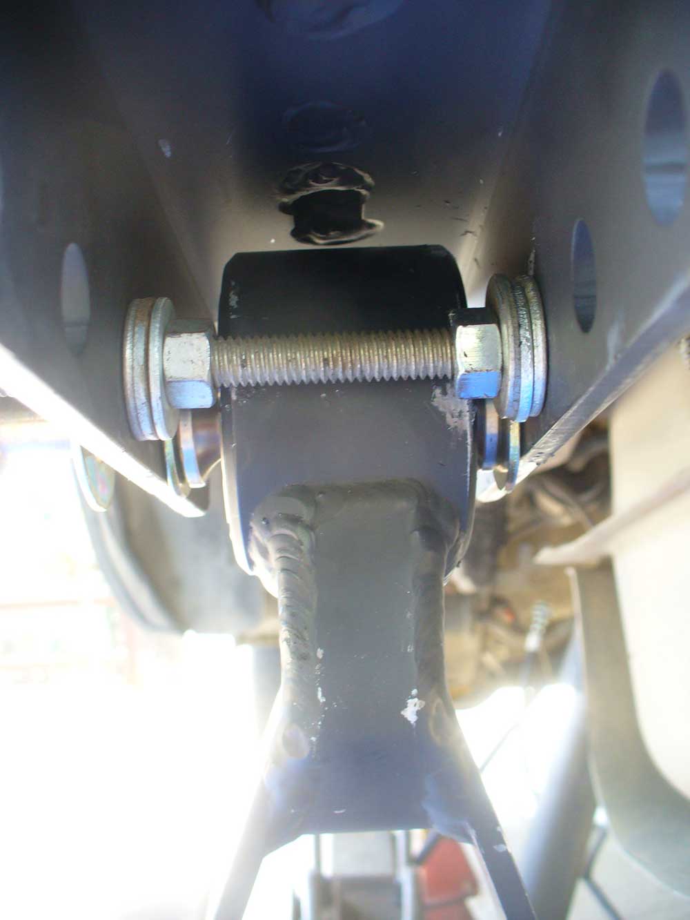
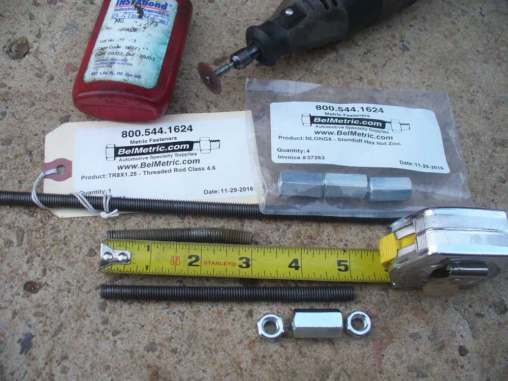
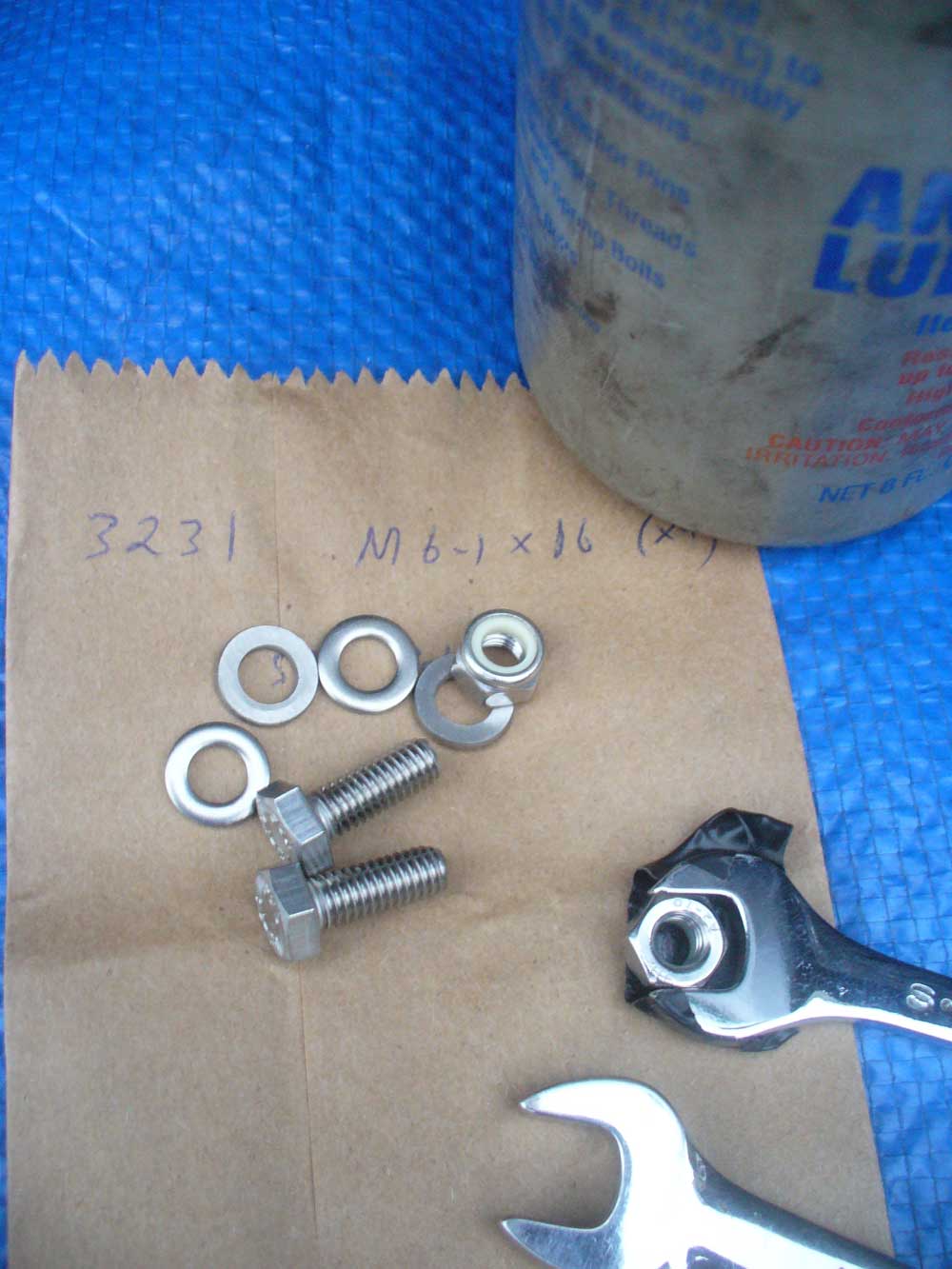
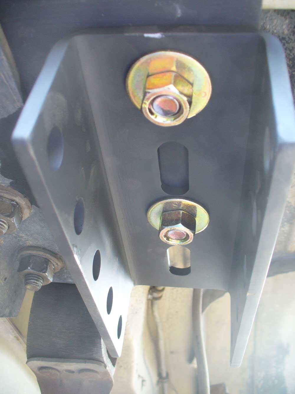
Then I mounted up the channels. I was not that keen on how little threads there are for the bolts. I like to see a couple of threads past the nut. That is not the only standard though. Here is a summary of the subject if someone wants to delve into it : http://www.portlandbolt.com/technical/faqs/recommendation-on-thread-engagement/
It seems plenty of folks are running these without any problems, so I went ahead with it like this:
Preface: This probably old hat to the experienced crowd here. For those who don’t want to be bored with the details, if you skip to the end I could appreciate some advice regarding the driveshaft angle, the speedometer sensor plug and shock absorbers. Thank you.
I thought the Thanksgiving weekend would be a good time to tear into what I hoped would be a quick project: Swap out my 3.07 geared 8.25 rear for a 4.10 geared 8.25. Should be a simple, straight up R&R type job. Right?
Well, just about exactly one month later I am finally able to drive my XJ around the block again. So much for my hopes. Oh well. False hope is still hope. But I did learn a couple of things in the process. Largely about what doesn’t work, but hey, that is a start, right?
3.07 gearing is pretty pathetic. And I didn’t get lucky enough to have my ’96 come with a 29 spline axle. A Dana 44 would be nice, but they don’t seem to grow on trees. However, I found a free Chrysler 8.25 on C/L, got a 29 spline factory Trac-Loc carrier from a fellow
member for the price of a couple six packs of beer, and a pair of Ten Factory 29 spline shafts were obtained from another member for about half the price of new. That seemed like a good starting point for an upgrade.I dropped off the parts at a local shop and had them provide the gears and full bearing kit. I also gave them an Iron Rock Offroad U-bolt yoke and a crush sleeve eliminator. When I picked up the axle they told me they chose not to use the crush sleeve eliminator because it did not register properly on the lands and they thought it would cut through the shims. I was not happy about this. I wish they would have called me at the time they found the problem. I could have turned a new sleeve of my own to whatever dimensions they wanted. Oh well. Next time.
The axle got wire brushed with an angle grinder, primed and painted.
The free axle came with a box of brake parts, both for it and for the previous owner’s replacement axle (I think a D44—certainly not another Chrysler 8.25). It was a mixed up mess, and the brake shoes and drums were soaked with gear oil. I decided to simply order all new brake components. Slave cylinders, spring kit, shoes and drums were all ordered.
Additionally, for some reason, the new axle was missing the brake lines, so I ordered a replacement set of lines from Fine Lines and a YJ flex line to deal with a previous owners solution, i.e. to simply remove the hard line from its bracket and just let it hang in free space. Yeah, that is a long term solution. :looney:
I figured I should be good to go.
[FONT="]Friday morning, after Thanksgiving I tore into things. Just getting into the job and then this happened:
[/FONT] Well, phooey. I hadn’t planned on needing new U-bolts. Yes. My mistake. I now know better. One thing learned.
The nice thing about Black Friday is that pretty much all local retail is open. I would have thought it would be no problem to run out and pick up another set of U-bolts, but the only place that admitted to having anything in stock for an 8.25 was Napa, and with them it was “Bring in what you have and we will try to match it.”
Well, they could match the diameter (for the axle tube), but not the length. What they had to offer was right about the length at which that one side snapped off.
Okay, fine. I had been wanting to ditch this stack of blocks and shims ever since I bought the Cherokee. It was time change this out to something better.
[FONT="]For some time I had been looking for a leaf spring pack that would net me 3” or so of lift, then I saw this thread about combining shackle relocation brackets and longer shackles to yield the same effect
http://www.naxja.org/forum/showthread.php?t=1134237
[/FONT] I have seen a number of threads and comments bemoaning the pleasures of dealing with the factory hardware for the leaf spring mounts. I already liked the idea of switching over to HD Offroad Engineering’s Shackle Relocation Brackets. Getting a bit of lift that way sounded like good sense to me.
Additionally, I had seen Boostwerks’ Comp Shackles thread in the vendors section and really liked the concept.
Relocation Brackets and Shackles had both been ordered and were on hand. Parts just weren’t quite prepped though.
Even for just a rattle can paint job I hate leaving hard corners. They don’t paint well and they do wonders to my knuckles when I find them the hard way. I went over everything with a file before giving things a quick sanding, priming and paint job. Even the new U-bolts needed to be painted (Napa’s U-bolts are bare, not zinc plated). That slowed progress down for most of a day. But I did have time to pull the rear bumper and hit the OEM shackle bolts with Kroil. And say a prayer that those bolts would come out gracefully.
The next day I got to move forward from where I was when the U-bolt snapped. The old axle was supported in place on three cheap mover’s dollies from Harbor Freight (I decided my back was more worth the $30 investment. That is a decision I would not have made when I was in my twenties.)
The new axle was then swapped with the old on the dollies, keeping the same arrangement so that things could slide into place gracefully.
Some new brake lines got installed on the axle at this point. I didn’t want to put them on earlier for fear of mangling them while moving things around, but figured there was less risk now that the axle was on dollies and it would be easier now than it would be once the axle was in place.
Previously, in order to compensate for the bit of lift from the blocks, someone decided to remove the hard line from its support bracket and allow for some extra freedom of movement:
I can just imagine the surprise problem when the hard line finally cracks. I had already ordered a hose for a ’90-’95 YJ to take care of that little detail.
The new axle did not come with the old hard lines, so I ordered a new set of those from Fine Lines.
And then I also needed to get the exhaust out of the way since I was going to have to access the hardware for the receiver. I had anticipated needing to do this someday. When I redid my exhaust system I flanged my muffler/tailpipe joint. That was a big help.
Finally it was time to go after those evil bolts. Kroil, prayer and a life without salted roads makes a difference. No problem at all getting those bolts out. They hardly even looked bad.
And the pockets looked fine too.
The shackle relocation brackets went in without any fuss. They are a nice snug fit, and a few blows from a mallet helped seat them. Pretty much exactly what I want in a fit.
I understand the ’97 and up XJs have something different going on at the very back which requires that the one corner be notched out. I had to do something to make up for that on my ’96 because my receiver needs that support there. I found a stack of three 7/16” washers was a pretty close match to the ¼” plate.
Then I mounted up the channels. I was not that keen on how little threads there are for the bolts. I like to see a couple of threads past the nut. That is not the only standard though. Here is a summary of the subject if someone wants to delve into it : http://www.portlandbolt.com/technical/faqs/recommendation-on-thread-engagement/
It seems plenty of folks are running these without any problems, so I went ahead with it like this: