• Welcome to the new NAXJA Forum! If your password does not work, please use "Forgot your password?" link on the log-in page. Please feel free to reach out to [email protected] if we can provide any assistance.

Dana 30 Build: Sleeve, Truss etc.... for 35's

nono, i mean go up, backward, in reverse.

Y link can't unload and roll you if its at the bottom. :)
 
nono, i mean go up, backward, in reverse.

Y link can't unload and roll you if its at the bottom. :)

I think your wrong about that. As Newton says, for every action there is an equal and opposite reaction. If I go up in reverse the rig wont flip over backwards but earth will now rotate out from under the rear of the rig causing the oceans will slosh, causing a collapse of the ice cap shelf's, causing a rising sea levels and a flooding of California.

Maybe its better if I keep this rig in Virginia.

John
 
You selfish bastard.

Could end our drought and want to stay dry instead
.
 
You selfish bastard.

Could end our drought and want to stay dry instead
.

Selfish Bastard, Arrogant Bastard what the difference?

On serious note:

I am concerned about my rear XJ D44 hanging too low. I considered shaving it but the more I thought about it, it seemed that shaving a D35 would buy me even more ground clearance since the pumpkin is so much smaller and if I put in a super 35 kit it would be plenty strong for 35's. Probably worth a new thread to get some feed back from others who run 35's on the Dana 35. Your thoughts?

John
 
On a serious note, how's your LCA clearance at the frame under compression?

The inboard lower control arms mount pretty far outboard. This was done to avoid contact between the drive shaft and the mounting tabs. As a result the long arms make contact with the frame rails under compression. I expected this to happen. On the driver side I needed to notch the frame rail just forward of where stock lower arms mounted about 1/2 inch so that after plated it over and closed off the hole in the frame rail I had about 1/4 inch clearance. The passenger side was far worse. The track bar is shorter than stock so the axle slides to the pax side considerably when the pax side is fully compressed. I had to cut out about an inch and go a couple inches up the side of the frame. Its a big hole. The solution here was to french in some 1/8 inch wall tubing so I have a curved pocket for the arm to move up into. The pic below is a zoom in of the frame mod so the resolution is pretty bad, but you get the idea.


Another little issue I had was that the Y link mount where it attaches to the long arm also makes contact with the frame rail when the driver side is fully stuffed. Again the frame rail was notched and a small section of tube as frenched in to provide a pocket for the head of the bolt that attaches the upper to the lower control arm.

I could have avoided all of this by just lowering the cross member an inch (like the BSfab guys did) and moving the inboard mounts more inboard but I was really working hard on getting the belly flat and slick.

John
 
i have the exact same issue. Guess I'll be chopping and plating the frame.
Go slow when you cut into it and be dang careful. The forward frame rail is divide into a upper and lower bay with a horizontal plate separating them. Try to only cut into the lower bay. The horizontal plate between the inner and outer frame rails gets closer to the bottom of the frame rail as you go back, completely closing off the lower bay 6 or 8 inches behind where the lower control arms use to mount.

Drill a 3/4 inch test hole low on the frame rail forward of the old lower control arm mount and look up inside there. Get a sense of where the spot welds are that secure the divider between the upper and lower bays so you dont cut those spot welds. trim slowly. I used a a really worn down cutting wheel and then switch over to a fiber backed dremel wheel.

The bending loads in the unibody are really big in this area and you to keep the moment of inertial as high as possible and retain the structurally stable two bay design of the original frame rail. Once you cut into the the divider you will not be able to get a welder inside the frame rail to weld it back on the plate you add to cover up the notch.

Also take care when you cut into the pinch seam. You must run a bead along the edge where the layers of sheet metal stack up on each other to get back the strength of the pinch seam as much as possible before welding the cover plate over the hole.

John
 
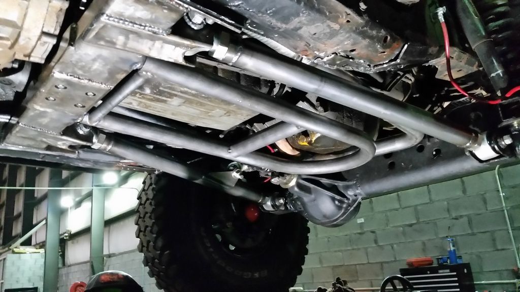
Front skid main tube work is done. Tube slips over two short stubs welded to the cross member. It will have a front strut on each side that run up to the plated frame inside the engine bay. Struts are pinned so I can drop everything out quickly if needed.

The main tube will be skinned with either 1/16th or 1/8th. Leaning towards the 1/16th material. Strength comes from the tube with the plate being welded all the way around the perimeter and to the cross tubes. Its not going to stretch or dent upwards 2-1/2 inches, which is what it would take to hit the tranny or oil pan.

John


1/6th will puncture though.

I'd go with 1/8"th at least. and skin it with UHMW

if you're worried about weight, weld some tabs on there and do 3/8" 6061.

looks great. need to get my exhaust routed like that so I can do the same.
 
1/6th will puncture though.

I'd go with 1/8"th at least. and skin it with UHMW

if you're worried about weight, weld some tabs on there and do 3/8" 6061.

looks great. need to get my exhaust routed like that so I can do the same.


How about just tabs and UHMW?

Nice work, BTW.
 
1/6th will puncture though.

I'd go with 1/8"th at least. and skin it with UHMW

if you're worried about weight, weld some tabs on there and do 3/8" 6061.

looks great. need to get my exhaust routed like that so I can do the same.

1/8th it is. I was concerned about 1/16th puncturing or tearing so hearing someone else have the same worry is very helpful. UHMW Poly Ethylene is a must have, and it has to go on before I bash this thing.

I hope the front struts turn out as nice as I think they will. Not much room between the arms and exhaust to get them up to the plated unibody.

John
 
How about just tabs and UHMW?

Nice work, BTW.

I wouldn't do it alone on an unsupported span. if he had a tube down the middle, maybe, but I have seen pointed rocks hit right and break unsupported sections of UHMW.
 
That'll be really cool when it's done. I wonder if it'll rattle with it just mounting one piece of tube over another.
 
It might rattle if thats all that I had holding it on. Since I also have to back up when high centered on it I need a way to keep it from sliding off the stub tubing. I will be drilling a hole through one side of each stub and then welding a nut inside the stub tube that is welded to the cross member. A bolt will then go into the nut through one side of the outer hoop. I cant cross drill it since I dont have space to remove a bolt that long. This will pull the two pieces together and prevent the outer tube from slipping off when backing up on the skid.

John
 
The skids have been skinned in 1/8th and are installed.


The front of the skid is supported by a strut on each side that goes up to the frame rail. The rear skid will have a single strut going up to the unibody offset to the driver side. Here is a detail of the strut on the passenger side.


For now its painted with a clear coat. The skids will get a single sheet of UHMW before seeing any rock work.

John
 
It LIVES


Up on a 42.

Not home yet , but close.

John
 
Back
Top