• Welcome to the new NAXJA Forum! If your password does not work, please use "Forgot your password?" link on the log-in page. Please feel free to reach out to [email protected] if we can provide any assistance.

No spark after engine swap...

Jared

NAXJA Forum User
Location
Ogden, UT
Okay, it all started when I turned a piston ring sideways in the original 4.0 with only 103k miles. I found a great condition 99 4.0 and swapped it in. For simplicity I kept the original '88 head and all the Renix electronics. The only thing that didn't have a home on the '99 block was the knock sensor, which is currently disconnected.

I have never been able to start this engine since installing it. I know that you are all thinking that I left something unplugged. Well, I have spent 5 hours today checking every single plug under the hood and they are all good. I had my dad look it over by himself to get a 2nd opinion and he could find nothing unplugged. I have checked every fuse in the vehicle. I have tested the ignition coil, and have tried 2 different ignition control modules. I have tried grounding a spark plug and plugging it straight into the coil, no spark then either. Tested the CPS and it's ok. Both yellow wires going to the ignition control module have power with the ignition on and the ground tests ok. The ground for the pickup coil (inside the distributor) is good as well. The ground straps are hooked up and test good to the motor.

The Jeep ran when the engine was pulled, in fact it ran great considering that it had about 60psi compression in cylinder #4. It's an auto, NP231, 4.0L, laredo, renix POS.

Question 1 - How do I bypass the knock sensor? Apparently it sends little pulses of voltage to the computer whenever it detects pinging. Does it do this by varying resistance, or does it actually produce voltage? Would a resistor or just connecting the 2 wires together bypass it? Leaving the plug dangling is the best way to go? Can somebody test the resistance across the 2 leads on their knock sensor for me?

Question 2 - What else am I overlooking?
 
There are two power supplies for the ECU, the one from the ignition goes out the left side firewall, all the way around the front of the engine bay and back to the firewall middle and into the ECU (go figure, must have been part of the French engineering). The other power supply for the ECU goes through a fusible link (at the starter relay) and is constant power.
They both go through connectors between the under hood relay block and the inner fender.
I once found a bent pin in a connector on mine.
Most of the in power for the sensors is five volts or so, which isn't going to pass through oil very well. Oily connectors is another possible.
No spark on mine, has been the CPS (though it did test good). The 5 or 6 (forget the number of pins) pin connector near the relay block and a disconnected MAP.
Poor spark has been a broken coil to cap wire. Moisture in the cap, moisture/oil in the ICM connector and corrosion between the coil and the ignition control module.
Have heard rumors, that the cam position sensor, can confuse the computer if the distributor is installed wrong. But I've had mine run just fine, with all the cables on cap, one lug off were they were supposed to be.
I´d put a compression tester on number one and rotate the motor till I got compression then align the timing mark and check to see if the rotor is pointing at the number one cap lug (or slightly after).
The ECU seems to make adjustments for some really sorry distributor initial setups, but I doubt it will accept any and all.
Really low battery voltage (or a really sorry connection) will also cause a no spark or a spark so weak it can hardly be seen, the starter sucks up most all the juice.
 
The knock sensor, the way I understand it, is pretty much a microphone. When it picks up an ignition knock it retards the timing.
A buddy broke the threads off of his in the block. After trying to remove the threaded part of the knock sensor for days, he threaded a chunk of metal to mount the knock sensor, that he spot welded to the side of the motor, over the stock location. A good solid sound conducting connection. Seems to work fine.
There are a couple of unused bolt holes on the left side of the motor even the fuel line bracket, that could be used to mount a solid piece of metal threaded to accept the knock sensor. All you really need is something to conduct sound. I don´t think I´d want to try and drill and thread the side of the block, you might get unlucky.
Unhookin it, jumping it or fooling it, would defeat just about the only really good part of the Renix system.
Just an opinion and an idea or two.
 
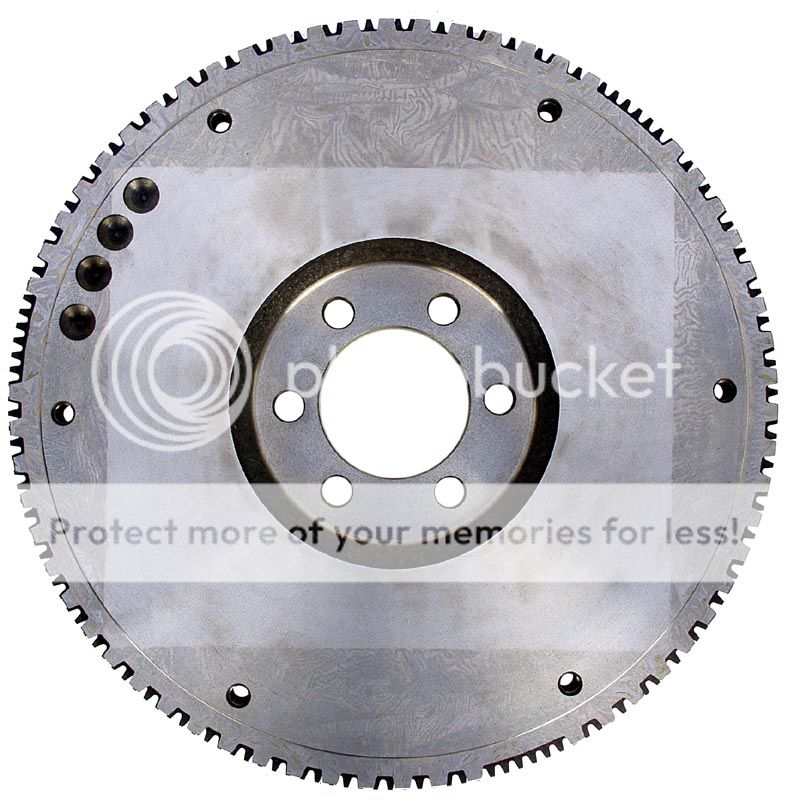
Did you use the newer flywheel?
 
8Mud - I've done the Top Dead Center check already, and checked for corrosion between the coil and ICM. I have not checked power to the computer yet though, which I will be doing shortly. Thanks

Old Man, I too gave that some thought. I honestly don't remember which flywheel I used. My Haynes manual says the CPS counts teeth on the flywheel, so I figured I was ok. Is there a set of different "teeth" on the older style flywheels that the CPS uses, rather than the teeth the starter engages to?

Thanks,
Jared:patriot:
 
If you used the new flywheel you are screwed. The two flywheels have a different pattern on the cps ring. The newer one has 4 holes spaced 120 degrees apart while the earlier has notches every few degrees with three large notches at 120 degrees. Here is a diagram of the one you need.
XJflywheel.jpg


You can check it by pulling the dust cover on the bottom front of the bell housing.
 
Last edited:
Wow guys, thanks for the helpful info. Guess I'll be pulling the dust cover tomorrow and checking this out. That would be awesome if I get to pull the engine again... Third time in a year.:yelclap:

Jared
 
Just to be clear, we are all talking about the flexplate when we say flywheel, correct? Also, is there some sort of extra piece that attaches to the flexplate with those patterned teeth? That's how the color picture posted by langer looks. Ok wait, I remember that now. The teeth are not flat (vertical) against the flywheel. They point toward the rear of the vehicle (they are horizontal), and they are on a thin sheetmetal type piece that attaches to the flexplate. Am I remembering this right?

Jared
 
Last edited:
If this is your problem don't feel too bad I did the same thing. It is quite annoying to have to pull the engine twice though. :laugh3:
 
Whats pictured is a flywheel. Its for a manual transmission. Since yours is an Auto, it will have a Flexplate. Its the same basic part though. The teeth in back of the flywheel pictured are the starter ring. Its for your starter to engage and turn over the engine.
Tom
 
old_man said:
...The newer one has 4 holes spaced 120 degrees apart...

I am going to assume that this is a typo. 4 evenly spaced holes would have to be 90 degrees apart. Does the earlier one have alot of smaller notches between the large notches too?

old_man said:
..the earlier has notches every few degrees with three large notches at 120 degrees...

Ok, I just checked it out as best I could working alone. Mine has many smaller notches between some larger (probably 2" wide) notches. The 2 large notches I felt were 90* or more apart. I thought I turned it 90* and felt nothing, but after turning it probably less than 10* more I found another large notch. It's a bit hard to do this accurately alone.

So, the newer tone rings have large notches every 90* while the older tone rings have notches every 120*? Is this right? Just gotta be sure before pulling an engine.... again.... and again.

Thanks again!

Jared:patriot:
 
That three groups of 4 holes 120 deg apart, with no teeth. So you have the older wheel and need the older Renix system stuff. Make sure you also are using the older CPS.
The picture I posted is for the Renix and seems to be what you have.
 
Last edited:
Yes I definately have a Renix XJ, and my tone ring definately has little notches which apparently makes it a Renix compatible part. Which means I'm good to go! HURRRRAY!

Oh, wait! My Jeep still doesn't have spark... Any other ideas guys? That last one had me plenty scared. I never had the '99 CPS, it stayed with the donor.

BTW - how do you pull codes on a Renix?

Jared:patriot:
 
Ok, so youve got the Renix CPS, flywheel, Renix distributor/ cam sensor, all the Renix electronics and the knock sensor is plugged in but hanging loose waiting for a home 2B found, right?

Well are you sure the CPS (and crank sensor which operates in a similar way) are installed right. These seem to have problems not because the hall-effect sensor itself fails but because their wiring connections become broken where they go into the sensor. Can you be sure these sensors are making good contact, are still intact, aren't bad and diddn't get broken when you pulled stuff apart? Also the ignition coil, its not putting out spark but does it get any voltage pulse at its wiring harness (analog voltmeter)? Its starting to look like a component (maybe even the computer but I doubt it) is bad.

The RENIX codes I believe require a RENIX compatible scanner to check, since it doesn't store or display codes.
 
When swapping engines you needed to keep the old:
distributor (make sure you put it in in the same position as the newer one you remove)
flywheel/CPS
ignition coil
TPS (you have to rig this up) & all other sensors

Did you keep your old head? I replaced the whole block/intake/exhaust.
I used all the original sensors from my 89 in the 93 motor I swapped in. I found a place for all of them to fit after a little searching except for one block temp sensor; I couldn't pull the new one out.

I had to use the 93 starter for some reason as the 89 didn't retract far enough.

I assume you have doublechecked for loose wires/grounds. Does it turn over?
 
Make sure you use the old CPS. I believe there is a difference between the Renex and the HO.
 
jfiscus said:
...keep the old:
distributor (make sure you put it in in the same position as the newer one you remove)
flywheel/CPS
ignition coil
TPS & all other sensors

Did you keep your old head?

All sensors are original. Flywheel appears to be original. The only thing that was used from the '99 was the short block, so from the head up it's an '88. I installed the distributor as per the TDC Compression Stroke instructions in my Haynes manual and double checked that with a 2nd opinion.

I've tested the CPS as much as it's possible, I believe for resistance across two wires - it's been a while but I did what it said to in the book and it was exactly as it was supposed to be.

Bajacalal - I do not show any voltage pulses from the distributor as the engine is cranked. I have tried this previously as I reaaaaly wanted to figure out a way to test the pickup coil inside the distributor (the book calls it a "sync sensor") and this was all I could figure out. I tried the analog meter set to it's lowest voltage setting (2.5VDC) and the needle didn't budge. I figured that being a hall-effect sensor, it wouldn't put out more than a half volt or so and wouldn't move the meter. Is there a good guideline for testing the pickup coil? I couldn't find a better way. The pickup coil has been my #1 suspect from day 1, becuase I got infinite resistance across every pair of wires going to it. It seemed like you should be able to measure resistance across a coil. So I even bought a new one and it tested the same so I took it back before installing it.

So, anybody know a good way to test the pickup coil? Or the ignition module (Autozone can't)?

Thanks for everything,
Jared
 
Back
Top