• Welcome to the new NAXJA Forum! If your password does not work, please use "Forgot your password?" link on the log-in page. Please feel free to reach out to [email protected] if we can provide any assistance.

Cut and Turn Pinion Angle

Francesco

NAXJA Forum User
Location
Ventura County
Hey guys, in the middle of shortening a HP 44 for TJ shafts, and I just cut the axle. I need to weld on the inner Cs, but I have a couple questions:

1. When setting the pinion Angle, I just set the diff to the desired pinion Angle, then set the C's with positive caster(the tops pointing to the rear of the axle), right?

2. Where do I set the angle finder to measure pinion Angle?

3. To measure caster I set it on the bottom of the inner c, right?

4. What is the desired pinion Angle for an xj on about a 4" lift? I looked but only found for 6+" of lift.
Thanks!
 
Hey,
Thanks for the tip, that's what they're suggesting for caster, which is right in line with what I was planning, however I'm stuck on the Pinion angle, rather than the caster.
Any other tips?
Thanks
 
The pinion angle should be 1-2 degrees above the drive shaft angle in the front and 1-2 below drive shaft angle in the back. Theoretically zero is perfect, but the offset allows for axle wrap under power. Although in the front you only have to worry about that in 4WD and with lock out hubs the front DS doesn't spin anyways.

To measure the pinon angle go off the pinion yolk or another vertical surface and on the the case go from the output shaft.

Yes, for setting your caster measure off the C bottom or top shouldn't matter.

Here are some more links.

http://cutandturn.com/basics.html

http://www.xjtalk.com/showthread.php?t=7354
 
Yeah, I would like to mock it up, I just can't weld anything on it to get it to sit and see, without welding the Cs on. The articles state that 13* is good for a 6" lift, but I'm on 3.5, so I know there is a measurement that will get me plenty close(caster is good from 4-8 ish so I have a few degrees of adjust-ability). I would measure my D30, however I don't know a common flat surface I can measure them both of of to check. Any other hints guys?
 
Why do you have to have fully welded C's to mock up the angles? Figure out ride height for the axle and then set you jack stands under the axle to keep it at that height. Mount arms and drop body down on coils till the weight of the vehicle is completely supported by the axle on the jackstands. Rotate pinion as needed, then measure for ideal caster at the knuckles and burn them in.
 
i didnt even go that far... i just put the axle on jack stands in relation to the body where i wanted it to be at ride height... positioned the pinion, measured acceptable castor. tacked in the link mounts. tacked in the coil mounts, (my Cs had already been cut and turned by the guy i bought my axle from) and pulled it back out to fully weld.

youre looking for "close enough" on pinion angle. i wouldnt sweat a couple degrees, most cheap angle finders are +/- 3 degrees anyway. point it at the case and go. physics says that yes, the pinion will dive under load (4wd), but i built my 3 link with all hard joints (heims) so the amount of deflection is very little.

if you want some sort of measurement just because... i measured castor off the top of the BJs at 6 degrees relative to true level. for pinion angle, i measured off the face of the yoke, knowing that the machined surface on the yoke is perpendicular to the centerline of the pinion gear. the difference between my castor and the pinion center line was 13 degrees. this has served me well at around 5" of lift and an inch of stretch in the front.
 
Thank you, that is some good data, which means you set your pinion angle around 8 degrees-ish, and It seems that somewhere around there and 10 should be okay-ish. If I set my caster for 5, and 10 degrees is too much, I can always add a few degrees of caster, not that I'd even be able to tell. Thank you! Stay tuned for some cutting and welding, here are some pictures if you're remotely interested of the process so far:

Cut and removed Inner Cs
2Itr7Rbl.jpg


My axle cutting-jig
ptREwiel.jpg


Finally, the cut axle. Still have to weld everything on!
laSv2ujl.jpg


My chromoly axle shafts - no fancy pictures yet, just stuff I've sent my buddies, I always forget to take pictures as I go. Inner shafts are from a TJ rubicon, and outers are Chevy shafts. I also have a TJ rubicon Artec Truss I'm gonna make fit.
tCduhuPl.jpg


BluetorchFab Hi steer arms with machined chevy knuckles
VrKUuIMl.jpg


Hoping to weld a bunch of stuff (probably gonna be 90% tack welded until I can get the car in the garage to mock up stuff) this weekend. We will see!
 
Well, its been a bit since, but I finally did it. Inner Cs put on for 8-9 degrees of pinion angle and 5-6 degrees of caster, and started mocking up my truss. Not fitting as well as I'd hope, but it's gonna be sick! TnT customs stretch coil buckets on their way as well, and now I need to cut the truss to fit the 3 link upper bracket, and start welding!

Here is the axle after cutting with the TJ shafts on, to see if they fit.
3uX8yXLl.jpg


Took the axle with me to work to weld it, made it a lot easier. Mocking up the angle for the inner Cs here.

gT1ne6Dl.jpg


Cs are on here, and truss is getting mocked up, looks good! Hopefully I'll be able to fill a few gaps when I finally weld it.

B1VRG0El.jpg
 
Nice! Are you fabbing your own 3 link or buying a kit?
 
I've been messing around with the 3 link calculator, and have a bunch of ruff stuff brackets, so it's gonna be home brew.

Here is what roughly I'm shooting for, passenger side 3 link.
OxYKv7Il.png
 
Right on, I've tried messing with the 3 link but still doesn't make sense. I read a bunch of stuff from Goatman on pirate. Few questions just to help me understand.

-Looks like your link separation is about 6" at frame and 8" at axle. What size tire are your running?
-Your upper link is shorter correct? I thought you wanted to have it either longer or close to the same length to keep pinon angle in line as suspension droops?
 
I'm gonna be running 35-37 inch tires, nothing bigger. 8-9" of separation should be plenty for that. If anything, I could always move the lower mount, here I have it parallel with the axle. From what I understand about the length, with a shorter upper you have similar caster throughout your range of articulation, which is much preferred for the street. This jeep is my DD.

Modified truss to fit the upper link bracket, way more annoying than expected, hopefully that link spot is gonna work, definitely tight as I'm only on 3.5" of lift...
vjKFBRvl.jpg


Close up
MCWuZmbl.jpg
 
From what I understand about the length, with a shorter upper you have similar caster throughout your range of articulation, which is much preferred for the street. This jeep is my DD.

Here's a quote from what I was reading about.

Upper Links: The upper link in a 3 link suspension can be difficult. Regarding length, there are some old and new rules of thumb. In the past, it was recommended to make the length 75% of the lower link length. Yes, this will keep your suspension geometry consistent during travel, but it can also cause the pinion angle to aim downward as the suspension droops. Instead, making the upper link the same length as the lowers (or even slightly longer) will allow the pinion to roll up along with the droop. Overall, equal length keeps the driveshaft alive and is especially useful for rigs with short wheelbases and/or driveshafts, or for low-pinion front applications.

Since you aren't probably getting crazy articulation on the street the castor will not matter as much as it should have already been set by turning your C's. Again I'm not expert, just trying to gather the most info I can for when I build mine. Looking good though, keep the post coming!
your train of thought is how i built mine. im not seeing gobs of travel on the street (nor seeing tons of street miles. but it goes down the highway just fine) so i built the arms to for superior pinion angle rather than castor during the range of motion.

12191021_897850806936003_1071248485462599663_n.jpg


with that said... i opted to put the upper on the drivers side. i wanted to control the pinion precisely. putting the upper on the passenger side and having it longer than the lower pushes/pulls the pinion in the opposite direction of what you want. if you do a longer upper, put it on the drivers side. with a 2D drawing, i found that the driveshaft really didnt extend/collapse much at all.

12246720_904008796320204_2536213963473337578_n.jpg


and i had originally started with the upper on the drivers side. but because of the reason stated before, i moved it to the drivers side.

18446666_1310539612333785_4744279745147766397_n.jpg


progress photo somewhere along the way.

1506601_958004860920597_5655149012522736988_n.jpg
 
with that said... i opted to put the upper on the drivers side. i wanted to control the pinion precisely. putting the upper on the passenger side and having it longer than the lower pushes/pulls the pinion in the opposite direction of what you want. if you do a longer upper, put it on the drivers side. with a 2D drawing, i found that the driveshaft really didnt extend/collapse much at all.

and i had originally started with the upper on the drivers side. but because of the reason stated before, i moved it to the drivers side.


/QUOTE]

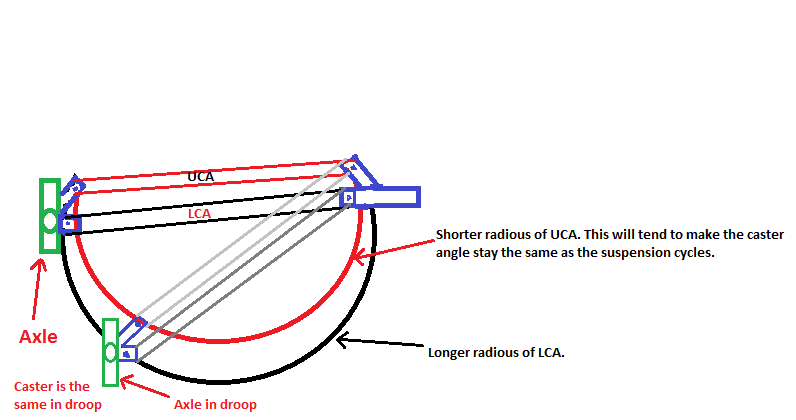
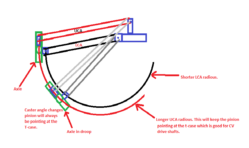
Thanks for the info. I've been reading trying to determine pro/cons of upper link placement. Overall, I gathered passenger works better because you have more "space". I wouldn't think the placement would affect the pinion angle. This diagram helped me understand it

These are real rough diagrams of how a short upper and a long upper should affect caster and pioion angle. The way I drew the radius is not real accurate, I should have drawn the circles bigger but I wanted them to fit on the paper. Hopefully this makes sense


shortUCA.png

LongUCA.png
 
ive seen those photos, and they make perfect sense.

if your goal is to control castor... put it where it fits. but in terms of pinion angle, the side is very important. our axles dont travel strait up and down when offroad, we articulate. the common radius arm is a good example of what i want to highlight.

as you droop one tire and compress the other, one radius arm is trying to rotate the axle pinion down, while the other is trying to drive it up. the same forces are true on a 4 link (with panhard). with these two situations, you HAVE to run a bushing somewhere in the system to take up the deflection of the opposing forces, or you will rip things apart.

this is why people say the 3 link removes bind from the system... it does. but with only one upper link controlling the whole axle, you need to be aware of where it is, or rather, what it is doing. you dont want it to be causing the pinion to dive as the drivers side droops out.
 
Hmm that's an interesting point I've never thought of.kinda shows we mock up and cycling the suspension can be so important. That being said, why does that seem like such a rare point brought up?
 
ive seen those photos, and they make perfect sense.

if your goal is to control castor... put it where it fits. but in terms of pinion angle, the side is very important. our axles dont travel strait up and down when offroad, we articulate. the common radius arm is a good example of what i want to highlight.

as you droop one tire and compress the other, one radius arm is trying to rotate the axle pinion down, while the other is trying to drive it up. the same forces are true on a 4 link (with panhard). with these two situations, you HAVE to run a bushing somewhere in the system to take up the deflection of the opposing forces, or you will rip things apart.

this is why people say the 3 link removes bind from the system... it does. but with only one upper link controlling the whole axle, you need to be aware of where it is, or rather, what it is doing. you dont want it to be causing the pinion to dive as the drivers side droops out.

Ok, I see what you are saying. That was one of the questions I've been searching for but couldn't get a solid answer. So just to clear it up, if running the upper link longer put it driver side if running shorter put it passenger side?
 
Back
Top