• Welcome to the new NAXJA Forum! If your password does not work, please use "Forgot your password?" link on the log-in page. Please feel free to reach out to [email protected] if we can provide any assistance.

"no bus" after wiring swap

spinaldex

NAXJA Forum User
Location
Oregon City, OR
So I've been working on swapping in a '98 PCM, Harness, Distributor, etc in my 2000 XJ. I've gotten it all in now and the motor kicks over (doesn't fire, but I still need to put in the distributor right, but thats a different story). When I turn the key on, it takes a few seconds and then the odometer reads "no bus". A few items on the gauge cluster don't work (battery volt meter for example) and the OBDII port for the reader doesn't send power (did pre-2000 even have them?).

Also, the Idle Air Control module keeps clicking over and over nonstop even if the key is off unless I disconnect the battery.

I'm wondering if this swap requires more components to be swapped, possibly under/behind the dash?
 
As an additional note, I also did the "gauge cluster reset" (park lights, hold trip reset, turn the key on, etc) and everything moves and lights up fine. But, the bus error shows up again after. I also noticed that the turn signals/hazards on the column are not doing anything.

I also verified all fuses were good in both fuse boxes.

Here's a more fundamental question then ... what does the turn signal and gauge cluster have in common? Is there a particular part of the harness that drives them both? Maybe something there isn't plugged in right from when I replaced the engine harness? Since I never touched anything behind the dash ... it has to be something I swapped.
 
Recheck all your work. Make sure all connectors are secure and that all grounds are clean and secure.

Try unplugging the CPS and see if the voltmeter and fuel gauge come back.
 
The gauge cluster test only tests the cluster function, not any of the PCM inputs or the wire harness it is connected to.

All the symptoms point to a short circuit or open circuit on the CCD Bus, or a failed CPS. The wire harness splices are prone to failure if flexed excessively, and you should look for wire damaged from melted or chafed wire insulation.
 
So, the going theory is this isn't some incompatibility between the cluster and the mix/match of years/engine harnesses, and instead that everything should work and its simply some crimped wires, broken connections, etc, right?

I went through and verified that all the grounds were connected to the body/block/etc and everything was clean by redoing them again. No change.

I unplugged the CPS and there was no change.

I guess I'll start stepping through the entire harness again foot by foot.

Thanks!
 
If you have a manual ranging digital multimeter you can check the health of the 5 volt reference voltage to the engine management sensors and the ground network that these sensors use.

The easiest sensor connector to get at is the MAP sensor. You can check at other sensors as well.

Remove the connector, turn the ignition switch to ON/RUN.

5 Volt supply: Touch the connector pin cavity with the ORANGE wire going to it with your meter (+) probe and the meter (-) probe to ground, such as the battery negative post. You should see 5.0 volts +/- .5 volts.

Ground Network: Touch the connector pin cavity with the BROWN/YELLOW tracer going to it (+) probe, (-) to ground. You should see .010 - .020 volts.
 
The gauge cluster on both model years communicate with the PCM via the 2 wire CCD bus. So there 'should' be no problem with the 2000 cluster talking to the 98 pcm, but if the 98 cluster is available to try, I'd do that to rule out communication.
 
The gauge cluster on both model years communicate with the PCM via the 2 wire CCD bus. So there 'should' be no problem with the 2000 cluster talking to the 98 pcm, but if the 98 cluster is available to try, I'd do that to rule out communication.

Communication issues with the CCD Bus can be checked from the DLC without swapping clusters.
 
I haven't looked for the SKIS box in the column, but the key I've used for years with the XJ is one of the black triangle ones ... not the tan ones. So, I'm *assuming* I've never had SKIS. What I can't verify is if the old owner taped one of the Tan chipped ones under the dash so he could use cheap keys which I heard some people have done.
I know SKIS won't allow the ignition to fire if the PCM is swapped and hasn't been flashed with the right VIN ... but would it do a "no bus" error as well? Ie, does this behave like that?
 
Ok. Then how are you to know from a digital multi-meter, that the IP is going to communicate with the PCM? Neither the meter, or a scan tool, will tell you if one does not communicate with the others
 
I haven't looked for the SKIS box in the column, but the key I've used for years with the XJ is one of the black triangle ones ... not the tan ones. So, I'm *assuming* I've never had SKIS. What I can't verify is if the old owner taped one of the Tan chipped ones under the dash so he could use cheap keys which I heard some people have done.
I know SKIS won't allow the ignition to fire if the PCM is swapped and hasn't been flashed with the right VIN ... but would it do a "no bus" error as well? Ie, does this behave like that?
No bus means there is no communication between the PCM and the IP.
A security lock out will not cause that.
 
All the symptoms point to a short circuit or open circuit on the CCD Bus, or a failed CPS

Any 97-01 XJ cluster will work in any 97-01 XJ. If the optional SKIM anti-theft is engaged, the engine will run for 2-3 seconds and then shut off. Remove the steering column plastic trim and look for the chip reader device at the ignition key cylinder.

.
standard.jpg
 
Ok. Then how are you to know from a digital multi-meter, that the IP is going to communicate with the PCM? Neither the meter, or a scan tool, will tell you if one does not communicate with the others

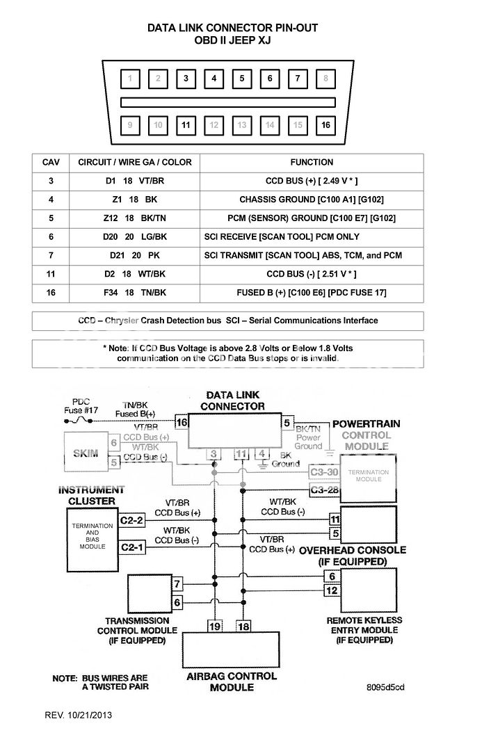
Here's how to check the CCD Bus, including the instrument cluster.

Refer to the schematic below.

You'll need a manual ranging digital Volt/Ohmmeter.

First you want to use your Ohmmeter, set to 200 Ohm scale.

Remove the battery negative post connector.

At the DLC, touch pin cavity 3 with your meter probe (+) and pin cavity 11 (-) probe. You should see 60 Ohms. If you see 120 Ohms one of the Termination Resistors is out of the loop. Usually the Instrument cluster but may be the CCD Buss wiring.

Next you want to check the CCD Bus + and - voltage.

Reconnect the battery.

Using your Voltmeter, set to 20 volt scale.

Turn the ignition switch to ON/RUN - do not crank or start the engine.

At the DLC, touch pin cavity 3 with your meter probe (+) and the meter probe (-) to pin cavity 4 and/or 5. You should see around 2.50 volts.

At the DLC, touch pin cavity 11 with your meter probe (+) and the meter probe (-) to pin cavity 4 and/or 5. You should see around 2.50 volts.

See schematic for limits.

If the voltage is out of spec, protocol is to start disconnecting the modules shown on the schematic until the voltage comes back to spec. Of course, the Instrument Cluster and PCM must not be removed because they are the bias voltage generator and Termination Resistors.

DLC.jpg
 
If you have a manual ranging digital multimeter you can check the health of the 5 volt reference voltage to the engine management sensors and the ground network that these sensors use.

The easiest sensor connector to get at is the MAP sensor. You can check at other sensors as well.

Remove the connector, turn the ignition switch to ON/RUN.

5 Volt supply: Touch the connector pin cavity with the ORANGE wire going to it with your meter (+) probe and the meter (-) probe to ground, such as the battery negative post. You should see 5.0 volts +/- .5 volts.

Ground Network: Touch the connector pin cavity with the BROWN/YELLOW tracer going to it (+) probe, (-) to ground. You should see .010 - .020 volts.

spinaldex,

Have you accomplished these tests?
 
Back
Top