• Welcome to the new NAXJA Forum! If your password does not work, please use "Forgot your password?" link on the log-in page. Please feel free to reach out to [email protected] if we can provide any assistance.

ASD Relay Electrical Problem

WildcatRider

NAXJA Forum User
Location
Nashville, TN
Yay.. back again with another XJ electrical problem.. just fixed a #22 Fuel Pump Fuse repeatedly blowing a couple weeks ago and now this. :smsoap:

Sorry this is long, but I provide as much info as possible to help you help me.

Driving to work yesterday, the Jeep suddenly died. Jeep actually started right back up, and I drove to work and back home last night. Started it this morning and it had a CEL.. drove it to work anyway. Also drove it home no problem, with CEL

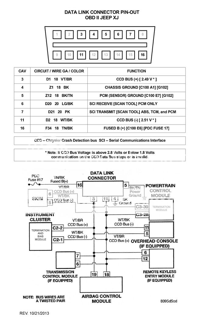
Got it home, saw P1694 (Fault In Companion Module, No CCD messages received from the powertrain control module). Cleared the code and tried to start it... started to turn over but then stumbled and started cranking. Now the thing won't start at all. Has CEL but no codes.

Replaced the crank sensor with a brand new Mopar part I had waiting just for this day, since I read that P1694 might be caused by that. Still no start.

Noticed that when I turn the key, the ASD relay buzzes/clicks very fast for the 1-2 seconds that the fuel pump is supposed to prime.

Testing (not sure what is relevant here)
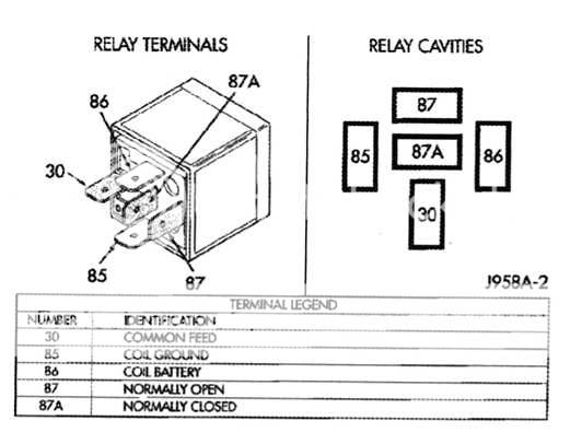
  • 12V from 86 to 85 during the 1-2 second prime
  • 12V from 30 to 87 (when I jump these pins the Jeep starts with no problem)
  • Full battery voltage from 85 to bat+ but 15 ohms from 85 to bat-

I have swapped the ASD relay with another one from the PDC, as well as one brand new USA made Tyco relay with the same results.

I am stuck.
 
I am on vacation today so I was looking at this for a while this morning, but I still can't understand why the ASD relay doesn't seem to be closing correctly. Does anyone have any ideas?

If I put a test light from 85 to 86, it lights up for 1-2 seconds when I move the key to run. Just when I replace with the relay it buzzes like it is refusing to pull over and stay there.
 
Sounds like low voltage or a bad ground (through the PCM) for the relay coil. Measure the voltage at fuse 11, it should be the same as the relay coil in (+) voltage. pin 85 (or C4), is most likely power in, though it may be power in on either the 85 pin (C-4) or the 86 pin (C-5). One is power, the other is switched ground, I always check both just in case. Assumptions usually cost time and rarely save time.

My 96 did that,. it turned out to be a dealer installed anti theft module that worked with the door lock key fob. The ASD relay was wired through the module. The module had a partially failed switch (electronic relay) that only let a trickle of current through, not enough to reliably close the ASD relay. I had the dealership remove the module and splice the wires together. A couple of months later one of their splices failed. I redid the splice job with a soldering gun.

Point is, it could be as simple as a corroded, dirty or loose connector someplace. Coolant on or in connectors conducts almost as well as a wire does. Coolant sucks moisture out of the air and stays wet and with the glycol added it conducts really well.

I remember thinking last go around, with the C22 fuse, thinking I don't believe that faulty harness was the whole story. I still think you have a sensor, wiring or relay short in there someplace. it may be as simple as a line leak through coolant to ground somewhere where it shouldn't be. When the voltage gets down to around 9 volts function gets iffy, 6 volts and it stops working in most cases. You can loose voltage between point A and point B, through resistance, line leak through water, mud, salt mixed with water or glycol. Most of those connectors aren't really water resistant, much less water proof. Loose, corroded or oily connectors can act just like big resistors and lower voltage. Bad grounds are the other half of the story.
 
Yeah.. I was just out there and came to a realization.. I am not sure how I missed this, but with the key out and battery voltage at 12.5, I have a ground at both 85/C4 (12.5 V to Bat+) and 86/C6 (12.05V to Bat+). From the FSM, 85/C4 is Start/Run+ and 86/C6 is PCM control (ground).

This is true on the ASD and Fuel Pump and they both source from F12 18 DB/WT / Splice 130 / Fuse 11 / Start Run. When I pull out Fuse 11, the test light stays on. I think this suggests the ground is between the fuse and the PDC?

Does this make sense? Sometimes I get ahead of myself.
 
When I put the key in run, and measure C4/85, I get 0.25V to Bat- and 11.9 to Bat+ with Bat voltage now at 12.15. Is that useful? Definitely seems like I have a short. My electrical experience only goes so far. I have good fundamentals but automotive wiring can be complex.
 
Sorry for multiple posts. I am running back and forth to the garage. With the key off and the test light between C4/85 and Bat+ (light turns on, which I think verifies the short) I should be able to browse around the wiring until the light starts to flicker right? Pulling F 11 doesn't change it, and I was moving wire harnesses all over the place and I see no change in the light.

Just want to make sure i am on the right track.
 
You want to check the voltage at fuse 11 with the ignition in the run position, then again at the 85 pin for the ASD relay. A 1 volt drop between the battery + through the fuse to the 85 pin shouldn't hurt anything.

The circuit between the ignition switch, to the fuse, through the fuse to the relay has splices and shared components. So getting a ground fault on the plus + side of the relay coil (85 pin) is expected. The important part is having enough voltage to work the relay, Like I said they get iffy at 9 volts and can fail completely at 6 volts or less.

I'd try checking the 86 pin for ohms to ground. I'm pretty sure it is a single wire to the PCM and should switch through the PCM to ground for a few seconds when the key is turned to run. Then switch to ground again while the motor is cranking over.

If the input voltage to the relay coil pin 85 is OK, maybe lightly split the coil out wire (pin 86), dark blue yellow and measure for standing voltage for the few seconds the relay tries to close when you first turn the key to the run position. It doesn't sound like the in voltage is your issue, it may be on the ground side of the relay coil, a connector, or even the switch (electronic relay) inside the PCM or maybe even the PCM ground.

I've got two handicaps going on here, one my eyes are (really) bad and two when I learned this stuff (auto electric) was in the mid sixties and the language has evolved (and I haven't kept up).

Any voltage you get in the ground side of the circuit with the relay under power is what I call standing voltage. It indicates how much resistance you have in the ground circuit, backing up voltage. Or you can just measure the ground circuit with an ohm meter.

Check the female spade connectors in the ASD relay socket for looseness and discoloration. Voltage may test good with a volt meter probe, but the relay pins may not be making good contact.

An easy way to troubleshoot is to print out the diagram, then use different color highlighter markers to trace the circuit sections as you are testing them. It helps avoid confusion and missing sections you should test in a systematic approach.

Test lights may not be the best way to troubleshoot something like this, volts and ohms are likely to be more productive. One thing you can use a test light for is to lightly prick, open the insulation to the copper core of the ASD relay coil out (ground wire) dark blue/yellow and test from there to battery negative. When you turn the key to run the light should blink out, then light again until you engage the starter, then the light should go out. if the light doesn't go out, you have some sort of ground issue either the ASD relay coil ground wire, a connector, the the ground switch inside the PCM or the PCM chassis ground.

I'm pretty sure fuse 11 should only have power with the key in the run or start postion, but the diagrams have been wrong before.

I may not be explaining this well, knowing it and explaining it are two different things.:)
 
Last edited:
Not ignoring this... had my family in town last weekend, and the in-laws coming in tonight for the weekend.. Just haven't had a chance to bury my head back in this yet. Really appreciate all the advice you have offered so far!
 
Last edited:
This result makes me concerned that I did not measure it correctly, but this is what I got.

With the key in RUN
Fuse 11: 9 volts
85 to bat neg: 3 volts

Key off
86 to bat neg: open when using continuity mode

Need to wait for a helper to check things during relay activation
 
Currently combing the wiring diagrams again. I discovered that if I turn the key to RUN with my hazard lights on, the combo flasher relay buzzes in the same way that the ASD relay buzzes during the time the fuel pump primes. It has been a few days since I checked it, but I think my A/C compressor and fuel pump relays were also buzzing at this time.

Starting to fear that the PCM is bad.
 
I'd be thinking ground before I'd think PCM. Most of those relays have battery power, either direct or switched and they activate on the ground side through the PCM.

I'm not saying the input power to the relay activator coil can't be deficient, the ignition switch or a splice may be causing issues.

One of the hardest things to troubleshoot is when you have a bad ground in one part of a circuit and the voltage backs up, there is sometimes no telling where the voltage is eventually going to ground. It can ground backwords through another leg of the power in circuit for some function totally unrelated.

I imagine we have all seen somebody hit the brake pedal and their brake lights come on and sometimes one turn signal (or park light) light also comes on, but usually dim. It is most always a ground issue someplace.

Ohm your PCM ground and/or volt test the PCM ground. Anv voltage you get in the PCM ground is voltage you can subtract from the input voltage for many relays. A good place to check is the battery ground and the smaller ground wires running to the same spot on the dipstick tube. The ring connectors for the PCM and TCU ground at the dipstick tube get corroded, they may be soldered on your year, they may not be, if they aren't soldered the corrosion can grow between the crimped wire and the ring connector crimp (the reason my TCU was screwing up). Also if the ring connectors for the TCU and PCM ground are behind the main ground cable from the battery remove everything check the ring connectors closely and reassemble with the TCU and PCM ground rings in the front and not behind the main ground cable. I also added some galvanized star washers, they make for a good contact. Be carefull trying to take the nut off the stud at the main battery ground by the dipstick tube, if you spin the stud things can get ugly fast.

I made some short jumpers for my relays, maybe four inches long, male spade on one end female on the other. I can hook up the relay and lay it on top of the whole works for volt testing and it helps to feel the relay work. Not something I use often, but easy enough to put together. Sure makes volt testing a lot easier.
 
Last edited:
A few observations/suggestions.

Did you really fix that F22 wiring problem? I reviewed your thread on this and your last post wasn't very clear as to what you did to fix this. Those sparks you saw may have had an affect on the PCM. The PCM is sensitive to voltage spikes.

Here's a few things you should do. Partial mechanical and partial electrical.

Mechanical:

Check/clean the PCM power grounds at ground G101 (see pic). Remove all the wire ring terminals at the G101 ground studs and scrub them using ScotchBrite pads and securely reinstall them. The wires at the oil dipstick tube mount bracket on your XJ are the grounds for the Data Link Connector and shouldn't be an issue.

G101.jpg


Remove the battery to chassis ground at G100 (see pic) and clean the connection as in for G101.

G100.jpg


Next, remove the ASD relay and inspect the relay pin cavities in the PDC for corrosion (black appearance). Check to see if the pin cavity connectors are not pushed down inside the PDC socket. Check to see if the pin cavities have been enlarged for pushing meter probes in them. You can assemble a tool made from a .250" wide spade terminal crimped to a section of wire and use it to insert into the pin cavities to see if they are a tight fit.

Verify the PDC is completely secure in its mount.

See if any of this has made a change to your issues. If not, go to the electrical checks.

Electrical:

Note: Put your test light away. Use only a high impedance digital Volt/Ohm Meter when checking circuits connected to the PCM.

As you know, the following actions occur when the starter motor is engaged: The auto shutdown and fuel pump relays are energized. If the PCM does not receive the camshaft and crankshaft signal within approximately one second, these relays are deenergized.

Here's the ASD relay PDC socket pinout and a photo of 86 and 85 written on the socket base for orientation purposes.

XJFuelPumpRelay.jpg


asdrelaysocket.jpg


Concerning your P1694, it may be a good idea to check the health of your CCD Bus.

Here's a schematic of the DLC and the modules on your CCD Bus.

Do these checks:

DLC.jpg


Key to ON (RUN), engine off,

Using your Voltmeter set to 20 VDC, touch DLC pin cavity 3 with meter (+) probe and pin cavities 4 and/or 5 with the (-) probe. You should see around 2.49 volts.

Repeat process at pin cavity 11 (+) probe. You should see around 2.51 volts.

These voltages may be higher or lower, and may be about the same, but never lower than 1.8 volts or higher than 2.8 volts.

If there is an extreme voltage you must isolate the cause.

Key to OFF (LOCK),

Voltmeter set to 2 VDC.

Measure the voltages at pin cavities 3 and 11. They should be around .02 to .150 volts each, which should be the difference between the voltages measured with key to ON (RUN), that you did above (Idle voltage).

~~~~~~~~

Concerning the ASD relay pin cavities you referenced in your previous posts, there may be a mistake. Refer to the relay pinout above.

86 is power from F11 with key to RUN, and 85 is ground circuit from the PCM.

I've found the following checks to be true for my functioning ASD:

Key OFF (LOCK),

Voltmeter set to 2 VDC,

Check the PCM idle voltage at relay pin cavity 85 to battery ground. You should see .02 to .150 volts. Or a very low voltage based on the idle voltage you found when checking at the DLC.

Key ON (RUN),

Voltmeter set to 2 VDC,

Check the PCM idle voltage at relay pin cavity 85 to battery ground. You may see a slight increase in voltage from the key off check of .02 to .150 volts.


If these checks show absolutely no voltage at all the wire from pin cavity 85 to PCM connector C3, pin cavity C3, may be open or shorted to ground. If this is the case, you should check continuity of this wire from 85 to C3/C3.

If you do find voltage when doing these checks, try wiggling the wire harnesses from the PDC to the PCM and see if you lose the voltages.

If still okay, there may a problem with the PCM picking up the flex plate rotation from the CPS and dropping out the ASD and fuel pump relays (within the one second window).
 
Your pdc has a bad connection in it, replace that portion of the wiring harness or splice in another pdc. I know it's alot of work and it sucks. I just went through this entire process.
 
So the holidays got in the way a bit, but I decided after hours of tracing wires and trying to find a short or bad ground and literally turning up zilch that I would order a PCM. This was easier since I work for the largest automotive parts recycling company in the USA, and my cost for a used PCM was $75 plus tax.

Just got home about 15 minutes ago and swapped the PCM and the Jeep started right up. I knew it would as soon as I turned the key to RUN because none of the relays buzzed.

Regarding Fuse 22, yes I am very confident I fixed that, and I think you are right, all that shorting out must have had an impact on the PCM. The wire was worn through and grounding out on the fuel rail. I re-taped everything, and put new loom around it, and zip tied it away from the fuel rail.

Thanks everyone for your help in this thread. I am just glad I wasn't one of the vast majority of cases that incorrectly diagnose a bad computer.
 
Back
Top